Getting Started With Lattice IceStick FPGA Using Open Source Tools on MacOS

The Lattice IceStick evaluation board is a great way into the exciting new world of FPGAs. It has opened up the traditionally closed world of FPGA development to hobbyists and makers. But working out how to install a development toolchain can be daunting, especially for Mac users. This tutorial is a step-by-step guide on how to bypass the official tools and install open source development tools for the iCE40 FPGA range, including the popular IceStick.
What is an FPGA?
Software has, for many years now, been encroaching on everything. From your smartphone to your car, from your fridge to your lightbulbs… they’re all running increasingly complex code on ever-advancing microprocessors.
But parallel to this, there has been a quiet revolution you might be less familiar with: software-defined silicon.
It has existed in more basic forms since the late 1970s. The very earliest programmable logic arrays (PALs) were only mask-programmable at manufacture, but soon after field-programmable versions using PROMs became available, and then EPROM versions in ceramic chips with windows, boasting a few dozen logic gates, could be programmed into whatever configuration the hardware designer chose.
Obviously, programmable logic became more advanced as time went on, devouring acronyms as it did so: PAL, PLA, PLD, PEEL, GAL, CPLD… until landing on the Field Programmable Gate Array, or FPGA.
FPGAs are many, many times more powerful than the early PALs: even the smallest typically boast thousands of logic elements, alongside blocks of RAM, dedicated I/O blocks and even DSP slices.
The Arduino Effect
For many years the whole programmable logic industry was closed, essentially inaccessible to individuals and hobbyists, because the cost of the evaluation boards and software tools was simply too high. Heavy hitters such as Xilinx and Altera ruled the roost, selling solutions to major electronics firms, and it was simply not in their interest to make their systems more affordable.
This is, incidentally, exactly how the microcontroller market was up until the mid 1990s. But along came companies such as Microchip and Atmel (now the same company) and started selling parts and tools at lower prices.
And famously, of course, the Arduino democratised the market forever.
So at long last, something similar is happening in the FPGA world. Perhaps the industry has learned a lesson, because now companies such as Lattice Semiconductor are doing what Microchip did in the 90s and making their eval boards available for hobbyist prices.
Enter the IceStick
The most affordable of Lattice’s offerings is the IceStick, priced at around $35-$40 and available on Amazon.
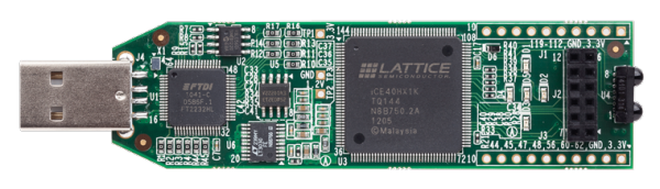
It’s based on a surprisingly large iCE40 FPGA, which is not as powerful as it looks, when compared to some of the smaller iCE40 packages, but nonetheless an extremely capable device that’s more than enough to get started with.
Crucially, its form factor is that of an oversized USB stick (hence the name), which takes care of the power and programming interfaces.
The board includes 5 LEDs, breaks out a couple of dozen I/O pins from the much larger number available on the chip itself, and, bizarrely, also has twin IR LEDs configured as an IrDA interface. Seriously, no-one ever used IrDA, which is why it seems such an odd interface to have on an eval board. But then, at this price, who’s complaining?
Plug a new IceStick into a USB port and you should see the LEDs blink in a sequencing pattern.
So far, so good. But how do you get it to do anything?
Hardware Design Languages
One problem newcomers encounter is that FPGAs are just so complex and alien that, if you just look at the specifications and block diagrams cold, it can be difficult to see how to use them. Those with any knowledge of digital hardware design will tend to start working out how to implement half-adders and shift registers in terms of logic gates; those with no hardware experience will just be confused.
There’s a strong analogy with programming: most programmers nowadays do not solve a problem by thinking about CPU registers and opcodes; instead they think about the algorithm they need to run and implement it in a suitable language, such as C, Python or JavaScript. They then leave the tedious task of turning the high-level code into binary machine instructions to the compiler or interpreter.
The equivalent in the FPGA world is the hardware design language (HDL). An HDL looks similar to a program, but instead of instructions it specifies a hardware design. It allows the programmer to define inputs and outputs, and also exactly what happens to those signals at any given moment. It abstracts away logic gates and lets the programmer think about solving the problem.
What is Verilog?
The two most common hardware design languages are Verilog and VHDL. This tutorial is going to use Verilog.
A great deal of modern hardware is not designed at the schematic level, but rather using software. It’s clearly faster, easier and more reliable to specify:-
module add(input [31:0] a, input [31:0] b, output [31:0] c);
    assign c = a + b;
endmodule
than it is to draw a schematic for a full 32-bit adder unit.
Scale this up to implementing, say, a RISC-V processor, and you can see that the software would start to look like a long program, whereas the schematic would be nightmarish.
Verilog is not a compiler, but a synthesis engine. It takes the HDL source code and turns it into an intermediate file of type .blif (Berkeley Logic Interchange Format). This is a low-level text file that defines the logic structure of the design, roughly analogous to the intermediate assembler language that is sometimes output from high-level compilers.
The rest of the toolchain takes this .blif file and turns it into a bitstream that can be programmed into the FPGA. A brief overview of the steps are included at the end of this page, but really the process is quite opaque and there’s little to gain by delving too deeply into it.
The Problem With Official FPGA Tools
FPGA manufacturers have traditionally sold bloated toolchains and IDEs that may or may not be any good, but the trouble was that so few people ever got to try them out. They were closed source, heavily licensed software that typically ran on Windows or, grudgingly, Linux.
Lattice also provide their own closed-source toolchain. They offer IDEs with a bewildering array of features. But if you check out their site, you’ll probably be left wondering exactly which tools you need, and whilst some are free, they’re not compatible with macOS. If you’re a Windows or Linux user and install any of the official tools, please do leave a comment about your experience.
Going Open-Source: Project IceStorm
I’d like to extend my thanks to Clifford Wolf for his excellent Project IceStorm. It contains all the tools you need to program the Lattice iCE40 FPGAs. The github page is where you’ll find the actual code.
Open Terminal and navigate somewhere you’d like to install the tools, then clone the repository:-
git clone https://github.com/ddm/icetools
Build the IceStorm Tools
Build the toolchain using the commands below.
First, navigate into the directory:-
cd icetools
and then kick off the build with:-
./icetools.sh
Now go for a coffee or beer. This will take a long time.
Build Error? No Sweat!
When it does stop, it may well have thrown an error like this:-
fatal error: too many errors emitted, stopping now [-ferror-limit=]
20 errors generated.
make[2]: *** [V3ParseLex.o] Error 1
make[1]: *** [../verilator_bin_dbg] Error 2
make: *** [verilator_exe] Error 2
If this happens, don’t worry! There’s a problem with the verilator simulator program, but it’s not an essential tool to use to the IceStick. Also, since verilator is the last component that’s installed, it means everything else should be fine.
(Note: If you really want to install verilator, you can just run brew install verilator.)
The important tools are yosys, arachne-pnr, icepack and iceprog. You can verify they’re all installed by typing the command names at the command line and making sure they all respond with something, even if it’s just an error message.
Hello, IceStick!
You need something to run on the IceStick in order to test your newly installed toolchain and the hardware. My HelloIce repo on github contains some bare-minimum Verilog code to check your setup. Download it like this:-
git clone https://github.com/leedowthwaite/HelloIce
Then just run the build.sh script followed by the name of the test, for instance:-
./build.sh green.v
This will build the green.v code and attempt send it to the IceStick FPGA.
Mac Driver Problem?
The actual build process should complete OK, but if you’re running this on a Mac, you’ll likely get an error when the programming tool iceprog tries to communicate with the IceStick. The message looks like this:-
init..
Can't find iCE FTDI USB device (vendor_id 0x0403, device_id 0x6010 or 0x6014).
ABORT.
Again, don’t panic, this is a known “feature” of iceprog on macOS. There’s an issue with the FTDI USB driver.
The easy way to fix it is to remove the driver:-
sudo kextunload -v -b com.FTDI.driver.FTDIUSBSerialDriver
Check the output of this command. It should say:-
com.FTDI.driver.FTDIUSBSerialDriver unloaded and personalities removed.
If it does not, and instead complains that there’s no driver, then your IceStick is probably not connected properly – I had issues with certain USB ports not recognising the device, which I fixed by plugging it into a different USB port.
If you do get the message that the driver has been removed, you should be good to go. Re-run the script:-
./build.sh green.v
and the programming should complete and verify OK. The green LED on the IceStick board should light up which means you’ve succeeded in programming the Lattice FPGA!
Blinking an LED
The next one to try is blink.v:-
./build.sh blink.v
This will cause one of the red LEDs on the IceStick to blink – the “hello world” of embedded systems.
The Verilog Code for blink.v
Looking at the Verilog code, it’s short and sweet, and includes some of the fundamental concepts.
`default_nettype none

// define a Blink module
module blink(input CLK_IN, output GLED5, output RLED1);

  // define a 24-bit counter to divide the clock down from 12MHz
  localparam WIDTH = 24;
  reg [WIDTH-1:0] counter;

  // run counter from 12MHz clock
  always @(posedge CLK_IN)
    counter <= counter + 1;

  // wire up the red LEDs to the counter MSB
  assign RLED1 = counter[WIDTH-1];

endmodule
The top level entity is a module. This is somewhere between a function and an object in programming. It takes inputs and outputs. It defines a 24-bit register called counter which is always incremented on the rising edge of the input clock. The output LED is connected to the MSB of the counter register so it flashes with a frequency of 12 MHz / 2^23 = 1.43 Hz.
The Physical Constraints File (.pcf)
The other important file is the icestick.pcf file, which defines the physical pins on the FPGA. Each line consists of:-
set_io identifier number
where identifier is the user-friendly pin name you’ll use in your code, and number is the device pin number.
If you look in the file you’ll see the user LEDs have already been given friendly names, such as:-
set_io GLED5 95
You’ll see GLED is an identifier referenced as an output of the main Blink module in the blink.v code.
You can rename the other pins to match their purpose in this file. So for instance, instead of:-
set_io J3_10 44
you might want to say something like:-
set_io H_SYNC 44
Then you could use the descriptive identifier H_SYNC in your Verilog code.
The counter.v Example
Finally, for something a bit more interesting than a single flashing LED, try the counter.v program:-
./build.sh counter.v
This wires up the top 4 bits of a 24-bit counter to the red LEDs so you should be able to see them counting in binary. The code is very similar to the blink sample, but it uses more of the top bits of the counter to create a more interesting pattern:-
Quick Overview of the build.sh Script
A lot of the steps of compiling the Verilog programming it into the FPGA are hidden behind the build.sh shell script. It’s is a great starting point as it avoids the tedious process of running each step of the toolchain individually.
But if something goes wrong in the build process, you need to at least know which part of the toolchain is failing.
The core of build script that invokes the actual toolchain looks like this:-
echo Using yosys to synthesize design
yosys -p "synth_ice40 -blif $MAIN.blif" $MAIN.v $@

echo Place and route with arachne-pnr
arachne-pnr -d ${DEV} -p ${PCF} $MAIN.blif -o $MAIN.txt

echo Converting ASCII output to bitstream
icepack $MAIN.txt $MAIN.bin

echo Sending bitstream to device
iceprog ${ICEPROG_ARGS} $MAIN.bin
$MAIN is the name of the file you want to build. You can see the script invokes, in turn, the following tools:-
yosys: the Verilog synthesis tool that takes the input Verilog file and produces a netlist that maps the code to the available logic blocks in the FPGA.arachne-pnr: the “place-and-route” tool that takes the.blifnetlist file output byyosysand turns it into a text-based bitstream representation. The bitstream contains the LUT values, block RAM contents and interconnection specifications.icepackpacks the textual bitstream into a binary format.binfile for the programmer.iceprogsends the binary bitstream to the FPGA’s EEPROM.
Conclusion
In this tutorial you’ve learned how to install the open source IceStorm tools and how to use them to program some sample code into the Lattice IceStick FPGA evaluation board.
There will be more tutorials coming on the subject of FPGA programming – make sure you join the mailing list to get regular updates!
Thanks for Reading & Get In Touch
Have you made something great with this? I’d love to see your photos and hear your stories. Please send me feedback, either by leaving a comment below or by contacting me directly.
And if you’d like to receive updates about my upcoming projects, please join my mailing list.
You can also follow me on Twitter.


Thanks for the interesting article. May I point to VerilogCreator/QtcVerilog which is a free/open-source Verilog IDE which runs also on Mac and also supports the IceStorm toolchain. Here’s the link: https://github.com/rochus-keller/QtcVerilog/releases/tag/v3.6.3
Please let me know if you’re looking for a author for your weblog. You have some really good posts and I feel I would be a good asset. If you ever want to take some of the load off, I’d really like to write some material for your blog in exchange for a link back to mine. Please blast me an e-mail if interested. Many thanks!