Introduction to IoT: Building a Budget, Single-Channel LoRa to MQTT Gateway
You don’t need an expensive LoRaWAN gateway to get started with IoT using LoRa. In this tutorial you’ll learn how to build a simple, single-channel gateway so you can experiment with a LoRa to MQTT gateway, and try out the unique properties of LoRa before investing any significant money into it.
One of the turn-offs hobbyists can experience when they first start looking at LoRa networks is the expensive overhead of buying or building a LoRaWAN gateway, and the overhead of dealing with cloud-based server architectures.
What About The Things Network?
When you start investigating LoRa, many online guides direct you to first check the The Things Network (TTN) map to see if there’s a LoRaWAN gateway running near your location. If there is, you’re in luck: you can activate your LoRa nodes for free with TTN and you’re up and running.
But if you don’t happen to live in a thriving IoT hub, there likely won’t be a gateway near you. At this point you’re casually advised to just buy or build your own LoRaWAN gateway, configure it and register it with TTN.
I don’t know about you, but that seems like quite an investment just to get my solar-powered greenhouse humidity monitor prototype working. A LoRaWAN gateway, even if you build your own, will easily run to a couple of hundred dollars, pounds or euros.
On top of that, I’m not sure if I even want the world and his dog to know about my prototype IoT nodes. Sure, LoRaWAN offers security, but this is just a test device. It’s a hassle.
Why Are LoRaWAN Gateways So Expensive?
When I first started investigating LoRa, I couldn’t believe there were no cheap gateways available. I scoured Amazon, eBay and AliExpress to no avail. Even the cheapest radio modules were at least ten times the cost of the Pi Zero W I’d envisaged controlling it.
So what’s the big deal here? Why so expensive?
Well, it turns out a proper gateway can demodulate no fewer than fifty signals simultaneously, theoretically supporting hundreds of individual nodes. It’s based on the Semtech SX1301, a much meatier lump of silicon than your cheap LoRa module.
So you can see why it would be great if they were everywhere: The Things Network would be huge, and we’d all be living in an IoT paradise.
If you really think you’ll have that many nodes nearby, either your own or in your neighbourhood, then go for it. However, where I live, I might install a handful of nodes, but I really don’t think my neighbours will have much use for them.
Time to look for an alternative…
Alternatives to a LoRaWAN Gateway
LoRaWAN itself can be used without The Things Network. There are other networks, private and open-source. LoRaServer is one such free solution.
And there are other protocol stacks built on top of LoRa, although many are commercial, such as Symphony Link.
One of these solutions might work. I’m quite keen to try the LoRaServer project at some point soon, but for now, just for the sake of learning and getting something up and running quickly, I’m going to roll my own gateway.
The Simplest DIY LoRa Gateway
If you’re not familiar with the LoRa physical layer, I recommend first reading my guide on everything you need to know about LoRa and LoRaWAN.
So I want to start with the simplest possible solution. These are the requirements I’ve decided upon:-
- A LoRa node will periodically report some environmental measurement as a short message;
- A single-channel LoRa gateway will receive the messages and convert them into MQTT messages which are then made available on my home LAN;
- An MQTT broker somewhere on the LAN;
- A client machine somewhere on my LAN can subscribe to the MQTT messages and receive and display the measurements.
It’s worth just outlining these requirements in a little more depth.
The LoRa Node
I’m not going to dive into this in much detail in this post. I’ll be publishing more posts about some of the LoRa nodes I’m developing soon. For this post, it’s going to report some measurements from a sensor. I’m going to use an ESP32-based LoRa module as the node (see the gateway section for an explanation).
Ultimately my nodes will be solar and/or battery powered, so I need to make sure the radio use is kept to the absolute minimum.
In the interests of extreme simplicity, the node will simply transmit a measurement up to the gateway periodically (say, once a minute for demo purposes, although in real life it would be less frequent). It will expect no confirmation. In fact, the node will receive nothing at all on the downlink.
The LoRa Gateway
This is the main focus of this article, so it’s where I’ll go into the most depth. The gateway is going to be an ESP32-based LoRa board, because it has on-board WiFi which means it should work without modification. Because I got a pair of these, I’ll use the exact same hardware for the gateway and the node.
The MQTT Broker
I briefly considered building the MQTT broker into the LoRa gateway but that would defeat the purpose of building the simplest possible gateway, and it would add a lot of custom code since out-of-the-box solutions like mosquitto do not run on the ESP32. It would also feel like a bad design because it would unnecessarily couple the LoRa packet forwarding function the MQTT broker, which may actually be serving a larger set of non-LoRa publisher devices.
Instead, I recommend running the broker on a dedicated Raspberry Pi, as shown in this tutorial.
Failing that, there’s nothing to stop an MQTT broker from running on the same machine as the subscriber. For this article I’ll do exactly that, because it’s the quickest and easiest solution, makes debugging easy, and keeps the number of moving parts down. This is not a solution for a final installation, just for development purposes.
If you’re unfamiliar with the MQTT protocol, or configuring brokers and subscribers, I recommend you read my article on building a simple MQTT subscriber using ESP8266, which is quite similar to what I’ll do here.
The Client Machine (MQTT Subscriber)
As mentioned above, for this I’ll be running a mosquitto client on the same machine as the broker, just for demo purposes.
Building the LoRa Gateway
“Building” is a strong word here. All of the work will be done in software. Because I’m using the ESP32 module with on-board LoRa and WiFi, there is literally no hardware work to do!
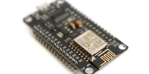
The Hardware: Heltec ESP32 LoRa Dev Board
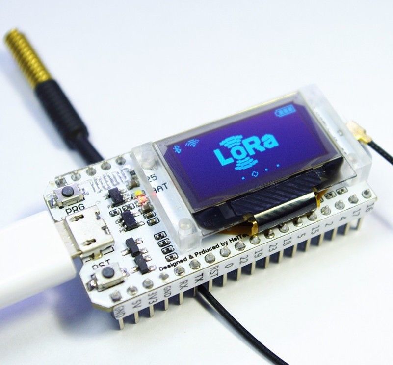
The Heltec ESP32 LoRa development module is an great little device, packing an Espressif ESP32 SoC, LoRa radio, antenna, WiFi, Bluetooth and even a 128×64 OLED display onto a NodeMCU form factor, all for about $20. It’s very convenient as I’ll be using its WiFi function as the “backhaul” to forward MQTT messages to my LAN.
Note on using different hardware
There are similar boards from different suppliers. They may well have the same guts: I don’t know because I haven’t tried them myself. But obviously you can substitute other hardware for this project. Just remember to modify the code to remove or update Heltec-specific parts.
For the gateway I’d still recommend an ESP-based module with on-board WiFi, because it’s cheap and small. For the the LoRa node, which doesn’t need WiFi, you could use any LoRa module with Arduino-compatible hardware. I only used a second Heltec module for demo purposes, because I bought a two-pack. In an actual installation I’d run a cheaper module with no display or WiFi, so I could power it from solar or battery.
To run code on the Heltec board, you’ll find it easiest using the Arduino IDE. You’ll find full, clear instructions for installing their ESP32 library and board configuration here: https://docs.heltec.cn/#/en/user_manual/how_to_install_esp32_Arduino.
The Gateway Software
The software is available on Github. There’s a few support files to deal with MQTT, LoRa and WiFi, but at its core it’s very simple. I’ve tried to keep the code fairly clean and non-hackish.
The setup function has to configure the Heltec board and on-board display, then the WiFi, the LoRa interface and finally the MQTT interface:-
void setup() {
   // initialise the board
   configureBoard();
   Serial.begin(115200);
   pinMode(LED_BUILTIN, OUTPUT);
   clearDisplay();
   displayString(0, 0, "Initialising Gateway…");

   // Initialise wifi connection
   initWiFi(WIFI_SSID, WIFI_PASSWORD);

   // Configure LoRa interface
   configureLoRa();

   // Configure MQTT connection
   if (isWiFiConnected()) {
     connectToMQTTServer(MQTT_SERVER, 1883);
   }
 }
Here’s the main loop:-
void loop() {
   // ensure WiFi stays connected
   checkWiFiStatus();

   // Perform packet forwarding
   checkAndForwardPackets();

   // MQTT housekeeping
   updateMQTT();

   delay(100);
}
The main loop() function just checks the wifi is still connected, calls the packet forwarder function (see below), and runs the MQTT loop.
The LoRa to MQTT Packet Forwarder
The packet forwarder is the key part of the gateway. It simply listens for incoming packets on the LoRa interface and forwards (publishes) them to the MQTT interface.
Let’s look at the code again:-
// checkAndForwardPackets()
// This is the core function that checks for received LoRa packets and forwards the contents on to MQTT
//
static void checkAndForwardPackets() {
   // check for received data
   String *rxPacketString = checkRxBuffer();
   if (rxPacketString) {
     // forward packet content to MQTT
     const char *msg = rxPacketString->c_str();
     publishMQTT(msg);

     Serial.print("rx packet: msg: ");
     Serial.println(msg);
     clearDisplay();
     displayString(0, 0, "received msg: ");
     displayString(8, 0, msg);
     displayRssi(rssi());
   }
 }
It calls the checkRxbuffer() function (in the file LoRaInterface.ino), to see if it returns a valid pointer to a String. If so, it converts it to a const char * because the subsequent function calls all require a C string.
It then calls publishMQTT() with the message. It also sends the information to the serial port and to the OLED display for debugging purposes.
Signal Strength (RSSI)
checkAndForwardPackets() also prints out the RSSI (received signal strength indicator) to give an indication of the signal strength at the gateway. This can be very useful when placing your node and gateway, and can also show if need need to increase any of the LoRa parameters such as spreading factor, coding rate, etc. (an advanced topic not covered in this article).
How to interpret RSSI
RSSI is the measurement that is used in your mobile phone to decide how many signal “bars” to show. It is a measure of power, expressed in dBm, which means “decibels relative to one milliwatt”.
dBm is frequently used to measure power in communication systems. On the dBm scale, 1mW equates to 0dBm. Unless the receiver and transmitter are practically touching, a radio will typically receive far less than 1mW via its antenna. In fact, usually a really strong signal would be around 100nW (which is expressed as -50dBm), but it could get as low as a fraction of a femtowatt (1 x 10-15 W).
These numbers are pretty small, and you soon get lost in decimal places, which is why the dBm scale is so useful. Because it’s non-linear, the scale is readable. For example, -100dBm is the lowest signal many wireless systems (such as WiFi) can reliably receive.
But LoRa, being a low-power system, can actually receive signals much lower than -100dBm. The specs say it can work down to -148dBm (presumably in a test environment), and I’ve seen it work in the real world (with a stubby little antenna) at -132dBm, which is still an incredibly small signal!
The LoRa Interface
All the LoRa radio complexity is hidden in LoRaInterface.ino.
At the top of the file is the configureLoRa()function:-
void configureLoRa() {
    // removed unused code for clarity
#ifdef USE_SPREAD_FACTOR
   LoRa.setSpreadingFactor(_spreadFactor);
#endif
   LoRa.onReceive(onReceive);
   LoRa.receive();
 }
The function first sets the spreading factor to the default value (which you can change to a higher value to achieve longer range, at the cost of a lower data rate).
Then it sets up a receive handler callback function. A callback is a function you want to be called whenever something happens. In this case, when the LoRa radio receives a packet, you want the onReceive()function to be called.
onReceiveis the most important function in this file. At the top of it there’s a comment:-
void onReceive(int packetSize)
{
   // Keep this short and sweet - it's an interrupt service routine
   ...
That’s important! If you already know about interrupts and ISRs, you can skip this next bit.
What is an Interrupt?
Traditionally, microprocessors can only perform one thing at a time. They run very fast, and input data tends to arrive much slower. In order to receive some input from a keyboard, for example, the CPU can do one of two things:-
- it can sit doing nothing except waiting for the next keypress,
- or it can get on with something else until it receives a message saying a key was pressed.
The latter option is almost always preferable, because if the processor was to sit waiting, it wouldn’t be able to do anything else. The screen would freeze, the mouse wouldn’t work and the network would appear to stop working. Obviously it would be better if everything else continued to work until the key was pressed.
The concept is called an interrupt. It’s a way of telling the processor that some event has happened, and that the processor now needs to go and handle it. In the keyboard example, it would go and fetch the pressed key and display the character on the screen, for instance.
Interrupt Service Routines
The code that handles the interrupt is rather special. It’s called an interrupt service routine (ISR). The important thing to consider about ISRs is that they’re called especially to handle the interrupt, while the processor was doing something else.
It’s impossible to predict what the processor will be doing when an interrupt occurs, because it can happen at any time. It may have been doing something very important, or time-critical. So for that reason, it’s imperative that the ISR runs very quickly and lets the processor get back to what it was doing.
Badly-written ISR code causes instability and will ultimately lead to a crash. To prevent this, the processor should spend as little time as possible executing the ISR and get back to what it was doing before the interrupt occurred. The ISR code should also change as few things in memory as possible, and those things it does modify should not be modified in many other places.
So-called race conditions can easily occur when variables are unexpectedly modified by ISRs. These problems are notoriously hard to debug, because they seem to occur randomly. So the best mitigation is to not let them happen, and keep interrupt service routines as small and efficient as possible.
The onReceive() Handler
As already mentioned, the onReceive() function is a callback, but it is called from the ISR that gets run when an incoming LoRa packet is successfully received. Because it’s called directly from within the ISR, it has the same restrictions as ISR code.
Here’s the complete function:-
void onReceive(int packetSize)
{
   // Keep this short and sweet - it's an interrupt service routine
   digitalWrite(LED_BUILTIN, HIGH);
   // Copy LoRa payload into buffer
   _payloadBuffer = "";
   while (LoRa.available())
   {
     _payloadBuffer += (char) LoRa.read();
   }
   // set flag to say there's data ready
   _receivedFlag = true;
   digitalWrite(LED_BUILTIN, LOW);
}
So, apart from flashing an LED, it only does two things:-
- Copy the received data into a temporary buffer;
- Set a flag to say the data is ready.
Retrieving Data from the Buffer
The boolean variable _receivedFlag is only set from within the receive handler, so it indicates to the rest of the system that a data packet has arrived. This allows the code to read the data at its leisure, without the constraints of executing inside an interrupt.
The code that does that is in checkRxBuffer() which you may recall was called from the main loop():-
// Check for recent incoming LoRa payload and copy it from the rxbuffer and pass it onto the caller.
//
String *checkRxBuffer() {
   static String payload;
   if (_receivedFlag && _payloadBuffer.length() > 0) {
     _receivedFlag = false;
     // ensure length does not exceed maximum
     int len = min((int)_payloadBuffer.length(), MAX_LORA_PAYLOAD-1);
     // copy String from rx buffer to local static variable for return to caller
     payload = _payloadBuffer;
     return &payload;
   } else {
     return NULL;
   }
 }
This function simply checks for the _receivedFlag Boolean to be set by the onReceive() callback, and double-checks that payloadBuffer string has a non-zero length. When these conditions are met, the _payloadBuffer string is copied to the function’s local string payload, which is declared static so that it is not freed when the function returns.
Now the LoRa message payload is returned to the caller (where it should be consumed immediately), and the _payloadBuffer can be safely overwritten by the ISR callback when next packet arrives.
It also clears the _receivedFlag so the same payload buffer is not read again.
The MQTT Publisher
The MQTT file contains all the functions for publishing MQTT messages and for creating and maintaining a connection to the MQTT broker. This functionality is covered in a fair amount of detail in this article.
The MQTT connection is configured by passing a hostname or IP address and port number to the connectToMQTTServer() function in the MQTT file.
There are some macros at the top of the main LoRaGateway file to keep them easy to find:-
// MQTT Broker info
// Define either an IP address...
//#define MQTT_SERVER   IPAddress(192, 168, 0, 2)
// ...or a hostname
define MQTT_SERVER   "Mac-mini"
Last but Not Least: Configure WiFi
Before you can successfully forward packets to an MQTT broker you’ll need the gateway to connect to your WiFi.
The WiFiSupport file handles all WiFi configuration. You’ll need to configure your WiFi SSID (access point / router name) and password at the top of the LoRaGateway file by modifying these macros:-
// WiFi credentials
 define WIFI_SSID     "*****"
 define WIFI_PASSWORD "*****"
Testing the Gateway
Testing with a LoRa Node
I tested the setup using another Heltec ESP32 LoRa dev board configured as a node (see forthcoming project for a proper node). It simply sends payload messages saying “hello N” where N is an increasing number.
Code to do this is very easy to find. The Heltec boards even ship with code pre-loaded that will repeatedly send this kind of message. If for some reason your board doesn’t have this, or you have overwritten it, then when you install the Heltec ESP32 library in the Arduino IDE it should be available as an example project, called WiFi_LoRa_32FactoryTest.
The code is also available on Heltec’s github page: https://github.com/HelTecAutomation/Heltec_ESP32.
Configuring the MQTT Broker
If you’re using a standalone MQTT broker such as a Raspberry Pi, you can skip this. But if you need to configure a broker, the easiest way is by installing it on your local machine, or even a virtual Linux machine.
Install and Start MQTT Broker on macOS
Install all mosquitto binaries using:-
$ brew update brew install mosquitto
Once installed, start the broker with:-
$ brew services start mosquitto
Install and Start MQTT Broker on Linux
Install mosquitto and the separate client package:-
sudo apt install mosquitto mosquitto-clients
On Linux, the modern way is to start it using systemd:-
sudo systemctl enable mosquitto
Windows
On Windows it will be different – please consult Google for the answers!
The MQTT Client
Once the broker is running, as well as the transmitter node and gateway, you can start a subscriber on the same machine.
On macOS or Linux, type:-
$ mosquitto_sub -h localhost -t "env/node1/temp"
localhost means the broker is the local machine, and env/node1/temp is the topic defined in the MQTT source file (see above).
Again, for Windows it may be different. Google will know more than me!
You should see output something like this:-
If it doesn’t work, check the serial monitor and display (if fitted) on the gateway. Make sure it’s connecting to WiFi OK, connecting to the MQTT broker, and receiving packets from the LoRa node.
Conclusion
This tutorial has demonstrated how you can set up a very simple LoRa to MQTT gateway using a pair of ESP32 LoRa/WiFi modules and by running mosquitto on a another machine on the network to act as the MQTT broker and subscriber.
In a forthcoming article I’ll show in more depth how to build a useful LoRa node to send real-world data to your MQTT client.
Thanks for Reading & Get In Touch
Have you made something great with this? I’d love to see your photos and hear your stories. Please send me feedback, either by leaving a comment below or by contacting me directly.
And if you’d like to receive updates about my upcoming projects, please join my mailing list.
You can also follow me on Twitter.


Hello,
congratulations for the beautiful article.
I also have two Lora Heltec V2s. If I use direct connection, as in this article, can I use 3 devices? Is this type of connection clear? Can anyone read the communication?
I also tried TTN with ESP-1ch-Gateway-v5.0, but it seems too complicated and slow for just two or three nodes.
A VPS cloud with Mosquitto and Node-RED seems like a better solution. I’m just worried about security. The communication between LORA devices should be encrypted, like the one between the MQTT client and Mosquitto.
Can you help me make these secure communications?
Thank you