Introduction to IoT: Build a Simple MQTT Subscriber Using ESP8266
Do you want to build a simple IoT device using ESP8266? With built-in WiFi, it’s a fantastic platform for IoT and home automation. In this tutorial you’ll learn how easy it is to build an MQTT subscriber that you can control with messages sent from anywhere on your network.
In the previous article in this IoT series, you learned how to build an MQTT server (or broker) using a Raspberry Pi. Now you’ll see how to build a simple MQTT subscriber using an Arduino-compatible ESP8266 device.
Why the ESP8266 is an Ideal MQTT Client
Espressif Systems’ ESP8266 has taken the IoT, home automation and hobbyist world by storm since becoming widely available in 2014. If you’re unfamiliar with it, here’s a quick lowdown of the features:-
- 32-bit RISC microprocessor
- Typically 4MB flash and 128KB RAM (80KB available to user)
- On-board WiFi
- On-board ROM includes bootloader and WiFi drivers
- I/O ports
- Arduino IDE support
They manage to fit all this into a module measuring approx 25mm x 15mm (including pins and antenna), and the raw modules are available for a couple of pounds or dollars each.
It’s already found in dozens of home automation devices.
Before You Start
You should have an MQTT server running before adding clients. If you remember from the introduction, MQTT clients include both publishers and subscribers. All the clients need a single server (called a broker in MQTT parlance) in order to pass messages between them.
If you’re new to MQTT then I suggest you read the previous article because it will not only introduce you to the core concepts, but it will also show you how to set up a simple MQTT broker and how to test it from your computer.
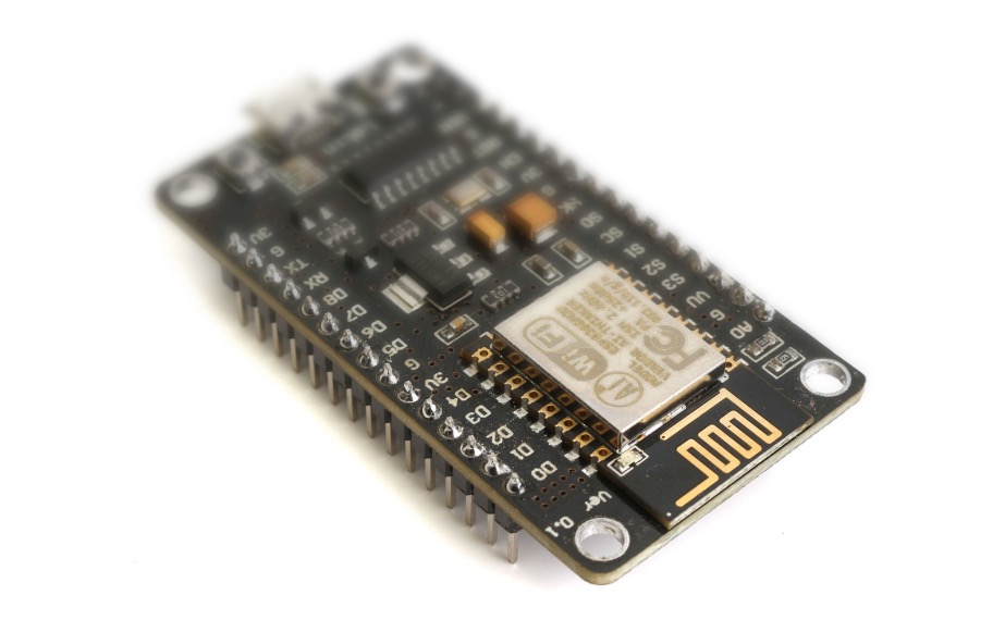
Choosing an ESP8266
It’s important to choose the right board. Some of the raw modules available on Amazon, eBay and AliExpress are incredibly cheap – in some cases less than a dollar. However, the really tiny ones are intended for use as a daughter board in bigger system: they come with no voltage regulator or USB interface for programming.
For development purposes it’s useful to have a more “plug-and-play” style module. The NodeMCU style is an ideal format. Many different clones and variants of this form factor are available, but typically they all feature a dual-in-line (DIP) pinout that allows them to be plugged into a breadboard for easy wiring, as well as a microUSB port on the bottom for power and programming.
Here’s one I’ve used myself: a MakerFocus NodeMCU board available on Amazon.
The NodeMCU form is also recognised by the Arduino IDE, which makes it straightforward to program.
I’ll be using a NodeMCU-style device for this tutorial.
Configuring Arduino IDE for the ESP8266
Important: The following steps assume you have already (a) added ESP8266 support your your Arduino IDE, and (b) configured the USB driver.
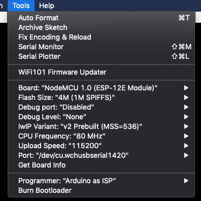
Follow these steps to configure the Arduino IDE for a NodeMCU-style ESP8266:-
- Launch the Arduino IDE
- Connect the NodeMCU to your computer using a microUSB cable
- In the Arduino IDE, under the Tools|Board menu, select “NodeMCU 1.0 (ESP-12E Module)”
- Choose the appropriate serial port driver from the Tools|Port menu
You settings should look something like this:-
Adding the PubSubClient Library
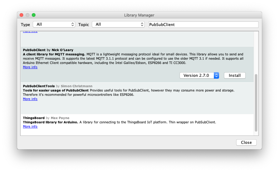
There are quite a number of Arduino-compatible MQTT clients available now. One of the best-known is PubSubClient, which works very well and is simple to use.
In the Arduino IDE, if you select the Sketch|Include Library > menu option and chose Manage Libraries… then you’ll see the Library Manager dialog. In the search box on the top right, enter the text PubSubClient and you should see in the search results. Click on Install.
Writing the Arduino Code
Now it’s time to write some code.
Global Constants and Variables
The following global constants and variables should go at the top of the file.
You’ll need the following includes:-
#include <ESP8266WiFi.h>
#include <PubSubClient.h>
Add a couple of macro definitions for convenience:-
// use onboard LED for convenience
#define LED (2)
// maximum received message length
#define MAX_MSG_LEN (128)
Now you need the WiFi config:-
// Wifi configuration
const char* ssid = "your wifi network name";
const char* password = "your wifi password";
And now the MQTT configuration:-
// MQTT Configuration
// if you have a hostname set for the MQTT server, you can use it here
const char *serverHostname = "your MQTT server hostname";
// otherwise you can use an IP address like this
//const IPAddress serverIPAddress(192, 168, 0, 11);
// the topic we want to use
const char *topic = "test/message";
Create the MQTT and WiFi stacks:-
WiFiClient espClient;
PubSubClient client(espClient);
Setup Function
Here’s the familiar Arduino setup function:-
void setup() {
  // LED pin as output
  pinMode(LED, OUTPUT);
  digitalWrite(LED, HIGH);
  // Configure serial port for debugging
  Serial.begin(115200);
  // Initialise wifi connection - this will wait until connected
  connectWifi();
  // connect to MQTT server
  client.setServer(serverHostname, 1883);
  client.setCallback(callback);
}
First of all the LED is configured as an output and turned off: logic high means off because the ESP9266 on-board LED is wired with inverse logic. You’ll use the LED later to show the status of MQTT messages.
Then the serial port is set up, and the WiFi configured.
Finally, the client sets the MQTT server address and the callback function. The callback function is explained below.
No attempt is made to connect to the server just yet.
Main Loop
The main loop is fairly straightforward:-
void loop() {
    if (!client.connected()) {
      connectMQTT();
    }
    // this is ESSENTIAL!
    client.loop();
    // idle
    delay(500);
}
The first thing the main loop does it check if the MQTT server is connected. If not, it calls the connectMQTT() function, which will wait until a connection is established. It’s important for the MQTT server to be running at this point.
Next, the MQTT client’s own loop() function is called. This is a vital step and no messages will be received is this is not called repeatedly from the main loop.
Finally the code waits a short time to save power and CPU like a good citizen.
Connecting to WiFi
The function to connect to WiFi is fairly straightforward:-
// connect to wifi
void connectWifi() {
  delay(10);
  // Connecting to a WiFi network
  Serial.printf("\nConnecting to %s\n", ssid);
  WiFi.begin(ssid, password);
  while (WiFi.status() != WL_CONNECTED) {
    delay(250);
    Serial.print(".");
  }
  Serial.println("");
  Serial.print("WiFi connected on IP address ");
  Serial.println(WiFi.localIP());
}
It begins the connection using WiFi.begin(ssid, password) and simply waits forever until it’s connected.
Establishing an MQTT Connection
The connectMQTT() function simply checks for a connection, and of none is active it attempts to connect to the MQTT server.
// connect to MQTT server
void connectMQTT() {
  // Wait until we're connected
  while (!client.connected()) {
    // Create a random client ID
    String clientId = "ESP8266-";
    clientId += String(random(0xffff), HEX);
    Serial.printf("MQTT connecting as client %s...\n", clientId.c_str());
    // Attempt to connect
    if (client.connect(clientId.c_str())) {
      Serial.println("MQTT connected");
      // Once connected, publish an announcement...
      client.publish(topic, "hello from ESP8266");
      // ... and resubscribe
      client.subscribe(topic);
    } else {
      Serial.printf("MQTT failed, state %s, retrying...\n", client.state());
      // Wait before retrying
      delay(2500);
    }
  }
}
A random client name is chosen for each connection attempt in order to prevent name clashes. The crucial piece of code is client.connect(clientId.c_str()) which attempts to establish the connection.
If successful, the client publishes a “hello” message on the topic test/message (defined globally at the top of the file). It then subscribes to the topic.
The Message Callback Function
One of the most important functions is the message callback function. If you remember in the setup() function, there was a line to register the callback function:-
  // ... inside setup() ...
  client.setCallback(callback);
A callback is a function that will get called from elsewhere in the code when something important happens. Often it is used by third-party library code so it can inform user code when some event is detected, such as data being received.
That is the case here. Because your user code has no knowledge of how the PubSubClient code works, you can’t edit the library code directly to make it do something when an MQTT message is received. So you register a callback, that is, you give the PubSubClient library the name of a function you want it to call when a message is received.
Because of the way C works, the callback must confirm to a predefined prototype, in this case:-
void (*callback)(char *msgTopic, byte *msgPayload, unsigned int msgLength);
This was defined by the creator of the PubSubClient library. It’s like a contractual agreement: the library agrees to inform you when a message is received, but its terms are that you must write a function that conforms to this prototype in order to receive the message.
If you’ve programmed languages that use interfaces or protocols then the concept is similar, but older and more primitive.
It can be called whatever you want, so long as the name is passed to client.setCallback(...). For simplicity it’s just called callback here. Similarly, you can name the arguments whatever you like so long as they are of the correct type and in the correct order.
OK, enough talk. Here’s the callback function:-
void callback(char *msgTopic, byte *msgPayload, unsigned int msgLength) {
  // copy payload to a static string
  static char message[MAX_MSG_LEN+1];
  if (length > MAX_MSG_LEN) {
    length = MAX_MSG_LEN;
  }
  strncpy(message, (char *)payload, length);
  message[length] = '\0';

  Serial.printf("topic %s, message received: %s\n", topic, message);

  // decode message
  if (strcmp(message, "off") == 0) {
    setLedState(false);
  } else if (strcmp(message, "on") == 0) {
    setLedState(true);
  }
}
The first thing it does is takes a copy of the message, which is then null-terminated to make it a C string. It’s important in this case because the code is going to interpret the message as a string, but there’s nothing in the MQTT protocol that says messages have to be strings: they are simply sequences of bytes, which could be interpreted in any way the application intended.
The array where the message string is stored is statically allocated just once, on the heap. The allocated space is that of the maximum message size the function accepts, plus one for the string-terminating NULL byte.
The final piece of the function just checks the message string. If it’s equal to “on” then the LED is turned on, and if it’s “off” then the LED is turned off. The helper function setLedState() takes care of the hardware details:-
void setLedState(boolean state) {
  // LED logic is inverted, low means on
  digitalWrite(LED, !state);
}
Does the Callback Have to Be Re-entrant?
You might have questioned the callback code for allocating the message string statically rather than creating a new buffer on the stack every time the function is called. What if the function were called again before the first invocation was complete?
If you did question it, then kudos to you, but your misgivings are unfounded. The callback does not have to be re-entrant, that is, it will not be called again before it has finished executing. For that reason it is safe (in execution terms) to use a static buffer to handling the incoming messages.
Because of the nature of the Arduino core’s simple scheduling system, all user code is executed from the main loop and all incoming messages are properly buffered.
In embedded systems it’s very common to use a static buffer in this situation. There are several reasons for this, but they usually come down to limited RAM and the desire to create deterministic code.
Non-deterministic code, such as when the stack gets too big, is often a source of difficult-to-find bugs. Keeping large buffer allocations off the stack helps prevent uncontrollable stack growth and reduces this kind of bug.
Testing the Client
Ensure you have another computer, virtual machine or Raspberry Pi with the mosquitto-client package installed. (It can be the same one the MQTT broker is running on)
Load the code onto the ESP8266 board and open the Arduino’s Serial Monitor to check it connects to the wifi and the MQTT server OK.
You should see something like this:-
Connecting to NETGEAR-AP
...

WiFi connected on IP address 192.168.0.21

MQTT connecting as client ESP8266-12ca...
MQTT connected
Now from the mosquitto-client machine, launch an terminal and type:-
mosquitto_pub -h mqtt-server-hostname -t "test/message" -m "on"
where mqtt-server-hostname is the hostname of your MQTT server. (Alternatively you can use its IP address.)
When you run this command, the following message should appear in the Arduino Serial Monitor:-
topic test/message, message received: on
And more importantly, the on-board LED should light up!
Send this message:-
mosquitto_pub -h mqtt-server-hostname -t "test/message" -m "off"
And the LED should now turn off.
Conclusion
In this tutorial you’ve learned why the ESP8266 is a fantastic platform for IoT. You’ve also seen how easy it is to implement a simple MQTT subscriber client on the ESP8266. There are virtually no limits on the possibilities for this combination of hardware and software!
Thanks for Reading & Get In Touch
Have you made something great with this? I’d love to see your photos and hear your stories. Please send me feedback, either by leaving a comment below or by contacting me directly.
And if you’d like to receive updates about my upcoming projects, please join my mailing list.
You can also follow me on Twitter.


Excellent tutorial, a great way to enter IoT for a beginner like me. In a few minutes I’ve been able to get a freshly received NodeMCU talk with my MQTT broker and interact with Node-Red
Thanks !
Thanks for the feedback Nicholas!
I think this is one of the most important info for me. And i’m glad reading your article. But should remark on few general things, The website style is great, the articles is really excellent : D. Good job, cheers
Thank you for this tutorial.
I want to control my system anywhere on the world by my phone. How can I create a interface on my phone? And how can I sent and read at the same time. One example; I want to give order like open and close and read some value like temperature. If it is to low then I can see the value on my phone and I can start the air conditioning. A kind of multi master system.
Thanks 🙂
Hi Tolga,
Thanks for the comment. Regarding creating an interface on your phone, there are two ways to do that: Either learn native coding for iOS or Android, and implement the interface that way. I outline this procedure for iOS in this article. Alternatively, you could run the interface on an embedded webserver (such as an ESP8266 or RPi) and use the browser on your phone to show the UI. But using this method, you may not even need MQTT since the entire webserver could run on the appliance you’re controlling.
Regarding your second question, which is basically a request-response model, this is often debated in the IoT community. It’s important to realise that MQTT is designed as a publisher-subscriber model, with one node publishing data and other nodes consuming it passively. The “standard” way to implement a request-response model over MQTT is to have two channels between each node, one for commands and one for responses. This can work, but it’s not ideal for many reasons, and if your system requires this architecture then maybe MQTT is not the right choice?
Hi Tolga,
if I want to send for example gps data from an IoT device and consume it passively by a backend server,
I need to do client.publish(url, coordinates); every few seconds, no?