Build an ATtiny44/24/84 Programmer Using an Arduino Nano
This tutorial will demonstrate how to build a programmer that can directly flash Atmel’s ATtiny
range of microcontrollers, using only an Arduino Nano and a few additional parts. The programmer will work unmodified with the ATtiny44, ATtiny24 and ATtiny84, and is easy to adapt to the ATTiny25/45/85 by reconfiguring the breadboard wiring.
Why Would I Use a Raw AVR Micro?
This tutorial came about because I was building a matrix keypad decoder for a security
system. I had prototyped it using an Arduino Nano (my favourite Arduino), but since the
keypad decoder was going to be merely a peripheral, connected via I2C to the rest of the
system, it seemed wasteful to use a complete Arduino in the final build. I wanted all the
electronics to fit neatly behind the keypad and the Arduino would have added too much depth
to the case.
Besides, it had been many years since I’d last programmed a raw microcontroller and I felt
like a challenge. And a quick google turned up a lot of conflicting information. Lots of
people have flashed lots of AVR chips with an Arduino, but I couldn’t find many using a
Nano, and of those that did, none were targeting 14-pin devices such as the ATtiny44.
What You Should Already Know
A few prerequisites are in order before we dive in.
In this tutorial I assume you’re already familiar with the Arduino IDE and hardware. As
this is a hardware project, I’ll also assume you understand the basics of electronics,
breadboarding and soldering. I won’t assume much else.
Buy Genuine Arduino Nano from Amazon
Background on Programming AVR Devices
Programming Microcontrollers: the Bad Old Days…
Not very long ago, programming firmware on microcontrollers was somewhat more difficult.
Proprietary toolchains, dedicated (and expensive) programmers, and outdated physical
interfaces were the norm. Programmers and SDKs typically cost thousands, as they were
aimed squarely at embedded systems professionals. The hobbyist did not even get a look-in.
In the 1990s, as a young graduate engineer, I used to write the code for my hobby projects
in the evenings, often with a “liberated” copy of a compiler. Then at work, during the
lunch hour, or staying late, I’d take the opportunity to use the company’s EPROM
programmers and UV erasers to actually get the code onto a chip. Of course, I wouldn’t
know if it worked until I got home, and then I’d have to wait until the next day to fix
any bugs!
By the mid 1990s it seemed as though tinkering with micros was a dying art. Chips were
getting ever more powerful but physically smaller. It seemed it would not be long before
every device was in a completely inaccessible BGA package. The internet was in its infancy
so there were virtually no resources for sharing designs and libraries, so everyone was
operating in isolation.
But in the late 90s things started to change. Microchip Inc. brought out their vast
range of cheap microcontrollers, made them widely available in a DIP package, and even
released an IDE that made them relatively easy to program and debug.
By the early 2000s I was amazed to be able to purchase a programmer for the PIC that cost
“only” a couple of hundred pounds.
Why Arduino Is Different
I only recount this to illustrate how far things have come and how lucky makers and
hobbyists are to have access to the Arduino system. For the most part, you do not have
to concern yourself with device programmers, fuse settings, etc.
Every time you press “Upload” in the Arduino IDE, your code builds and is magically sent
to the Arduino via USB. There’s actually a lot going on under the hood here that you are
blissfully unaware of. One of the factors that has made the Arduino so appealing to
hobbyists for so long is the ease with which you can deploy code to the hardware.
The Arduino Bootloader
There are several things that make an Arduino an Arduino, not least of which is the
bootloader. It is the bootloader that allows you to program the microcontroller
without a dedicated programmer.
The bootloader is a small (approx 500 bytes) program that lives in the Arduino’s flash
memory and, every time the chip is reset (via the DTR signal from the USB/serial port) it
looks for a particular signature of bytes on the UART, and if they are seen it emulates
a hardware programmer and writes the program image received over the UART to flash memory,
obviously avoiding overwriting itself.
Chicken & Egg: So How Does the Bootloader Get There?
So you’re probably wondering how the bootloader code gets into the AVR in the first place.
Obviously the bootloader cannot load itself. It seems like a paradox.
The simple answer is that it is programmed using the in-system programming interface.
This is a special interface that Atmel has built in to all AVR chips to allow the device
to be programmed “in the field”, or in other words, when it is installed in its final
system rather than beforehand.
We seem to have two choices when programming a raw AVR microcontroller: we can use the
bootloader and a serial (or USB) port, or we can use ISP. But since the bootloader itself
must be installed via ISP, it turns out we only have one choice: in order to do anything
at all, we must implement ISP. And once we’re able to do that, there’s little advantage
bothering with the bootloader at all.
Overview of In System Programming (ISP)
In-System Programming, or ISP, is a generic term in embedded systems that means
re-flashing a device without removing it from its target system. When ISP-capable devices
first arrived on the scene it was like a miracle. Previously, for every tiny change to the
code, the target system had to be opened up, the device levered out of its socket and
put into a programmer attached to the development system.
There were a couple of reasons for this. One was that programming required a “dangerously”
high 12V voltage to be applied to the chip, something that would generally fry the rest of
the 5V digital parts of the host system, so removal was a preferred option. But that was
possible to overcome, and the real problem was that traditional programmers used to
transfer the data into the chip using proprietary, often parallel bus, systems.
With ISP the developer could now leave the chip in situ and happily re-flash the code as
often as he or she liked. It felt like the chains had been thrown off!
ISP vs ICSP
Atmel’s implementation of ISP is known as ICSP, or In-Circuit Serial Programming. People
use the terms ISP and ICSP interchangeably: they mean the same thing.
On Atmel’s AVR chips the program data is transferred using the very fast and lightweight
3-wire synchronous serial interface (SPI), using the special ICSP protocol. Blocks of data
are transferred to the target device and written to the flash program memory under normal
operating voltage. If a higher programming voltage is required, it is safely generated
internally.
Getting Started: Building an ATtiny44/24 Programmer
Overview of the Project
Here are the steps we need to take to build a working ATtiny programmer using an Arduino
Nano:-
- Configure the Nano as an ISP programmer using ArduinoISP
- Build a circuit to connect the Nano to the ATtiny44 or similar device
- Load the ATtiny24/44/84 board configuration into the Arduino IDE
- Test the ISP by flashing some code
I’ll detail each step below. If you’re confident that you know enough about a particular
step, feel free to skip it.
Step 1: Configure the Nano as an ISP programmer using ArduinoISP
So what’s the quickest way to build an ISP for our AVR chips? It would be really great if
we could find a ready-made device that had the SPI interface and a bootloader so we could
avoid the chicken-and-egg scenario and load code into the programmer from a USB port, and
then use the SPI interface to transfer program data to the target device.
Of course, such a device already exists: it’s called an Arduino. And what’s more, we don’t
have to write any specialist code: the good folks of the Arduino community have already
done it for us!
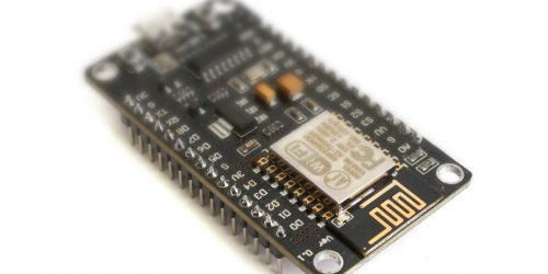
To configure an Arduino Nano as an ISP, simply open the Arduino IDE, connect your Nano
using a USB cable, and in the Tools|Board Type menu, select the Arduino Nano. Then go
to File|Load Sketch and choose the ArduinoISP sketch. Upload to the board and voila!
Your Nano is now an ISP.
You won’t be able to do very much with it until you’ve built some hardware to connect it
to an ATtiny chip. That’s what we need to do next.
Step 2: Build a circuit to connect the Nano to the ATtiny device
The majority of the ArduinoISP designs scattered around the web feature an Arduino Uno
connected to a target AVR using a breadboard. Having the target device in a breadboard is
a great option because it allows us to program any device if we can figure out the wiring.
However, I wanted a permanent programmer and so I didn’t want the whole circuit to be on
breadboard, only the parts that need to be configurable: namely, the ISP signals and power
rails going to the target device. These will be the ones most likely to change when
programming a different device.
It’s worth noting that I could have used a ZIF (zero insertion force) socket for the
target chip, but let’s consider the pros and cons for a moment.
Because all AVR chips have different pinouts (not to mention non-Atmel devices such as the
ESP8266), I would have had to figure out a scheme to configure the programmer to route the
power and SPI signals to the correct target device pins. A whole load of line driver ICs
or – more likely – an FPGA would have been the “proper” choice here, which would have made
this project many times more complex. A much simpler configuration scheme using jumpers
would have been easier, but that still increases the complexity a lot, leaves a lot of
room for wiring errors and is unlikely to exhaustively cover all possible (including
future) target devices.
So the compromise I opted for was to have a “motherboard” which holds a socket for the
Nano module, all the programmer status LEDs, a 6-pin IDC ribbon cable to connect to the
ICSP header on the Nano, sundry components and a breadboard for the target chip.
Buy DEYUE Solderless Mini Modular breadboard Kit on Amazon
Let’s look at the parts of the motherboard circuit in detail.
Arduino Nano socket
The Nano sits in a socket on the motherboard. This allows it to be removed if needed for
another project, or replaced in the event of damage. It also prevents possible heat
damage during soldering (although in my experience such fears are generally overblown).
There are very few signals brought from the Nano through the main socket down to the
motherboard. These are described below:-
+--------+-----------------+-----------------------------------------------------+
| Signal | Purpose         | Notes                                               |
+--------+-----------------+-----------------------------------------------------+
| GND    | Ground rail     | Common ground                                       |
| /RESET | Arduino reset   | Tied to GND via a capacitor to stop unwanted resets |
| D10    | Target reset    | Connected to target /RESET pin, to reset target chip|
| D7     | Programming LED | Indicates the target is being programmed            |
| D8     | Error LED       | Indicates the ISP has encountered an error          |
| D9     | Heartbeat LED   | Indicates the ISP is running OK                     |
+--------+-----------------+-----------------------------------------------------+
Connecting the ArduinoISP Status LEDs
Note that the status LEDs are optional and are often omitted in tutorial designs, to keep
the breadboarding simple; however, they are immensely useful when you encounter problems
programming a target device.
I used green and red LEDs (actually a green/red tricolour) for the heartbeat (D9) and
error (D8) LEDs, respectively, and a blue LED for the programming LED (D7).
ICSP and SPI Signals
Many older tutorials tell you to use Arduino pins 11, 12 and 13 as the SPI signals to
program the target. This is because the SPI signals are available on those pins on some
Arduino models such as the Uno, Duemilanove, etc, including the Nano, but not on many
others including the Megas, Leonardo, Due, and Zero.
The mapping is as shown:-
+---------------+------------+
| Arduino Pin   | SPI Signal |
+---------------+------------+
|   11          | MOSI       |
|   12          | MISO       |
|   13          | SCK        |
+---------------+------------+
The code that defines this within the ArduinoISP sketch is:-
    #ifdef USE_OLD_STYLE_WIRING

    #define PIN_MOSI    11
    #define PIN_MISO    12
    #define PIN_SCK     13

    #endif
One of the features of the ArduinoISP code is that you can actually assign these PIN_xxx
macros to any digital output and the code will emulate the SPI hardware by “bit-banging”
the output. There are some restrictions on clock speed here – obviously if your Arduino
is clocked too slowly then the emulated SCK speed will fall outside the spec of the ISP
protocol and not work.
Whilst this is doubtless very useful in certain circumstances, in the vast majority of
cases there is no good reason to use these, or any other, digital output pins when
virtually all Arduinos have a perfectly good ICSP header which already breaks out the SPI
signals in a consistent pinout.
Note that there is some potential for confusion here – it certainly confused me for a
while. The ICSP header is actually intended for programming the Arduino from another ISP.
This makes sense when you think about it – most people don’t use the Arduino as an ISP so
why would it have a built-in ICSP header for that purpose? However, because all the
signals we need for being programmed via ISP are also used for programming via ISP, it is
only logical to use them.
The ArduinoISP documentation tells us to use the ICSP header, so that’s what I will do in
this project. The ICSP header signals are described below:-
+------+--------+--------------------------------+----------------------------------+
| ICSP | Signal | Purpose                        | Notes                            |
| Pin  |        |                                |                                  |
+------+--------+--------------------------------+----------------------------------+
| 1    | MISO   | Uplink data from target device | SPI data signal                  |
| 2    | SCK    | Serial Clock                   | SPI clock signal                 |
| 3    | /RESET | Reset the Arduino              | _Unused when Arduino is the ISP_ |
| 4    | Vcc    | 5V power rail                  | Target device power              |
| 5    | MOSI   | Downlink data to target device | SPI data signal                  |
| 6    | GND    | Ground rail                    | Target ground rail               |
+------+--------+--------------------------------+----------------------------------+
We connect to the ICSP header using a 6-way ribbon cable with a 2×3 IDC socket at each
end. One end connects to the Arduino’s ICSP header, while the other connects to the
“motherboard” near the breadboard. Here the signals are broken out to IDC headers so they
can be connected to the breadboard using jumper wires.
The only ICSP signal we will not be using is the /RESET signal, which is tied to the
Arduino’s /RESET pin so it can be reset from an external ISP. Of course, this is not what
we want, and instead we need the Arduino to reset the target device, so we use output
connected to the target’s /RESET pin to initiate programming. For this we use D10 as
defined in the ArduinoISP code:-
#define RESET 10 // Use pin 10 to reset the target rather than SS
This signal is brought down via the Nano socket as described above, and it is also broken
out on and IDC pin near the breadboard.
ICSP Cable Orientation LED
The ICSP cable should use keyed plugs and sockets to ensure correct orientation and
prevent damage to the target device. In addition, I put a green LED with a 330 ohm
resistor on the motherboard between ICSP pins 4 and 6 (Vcc and GND) in order to give a
visual indication that the cable is correctly oriented. If the LED does not light when the
Arduino is plugged into a USB port, it means the ICSP cable is incorrectly wired.
Schematic
The schematic for the Arduino Nano-based ISP is shown below.
The Finished Circuit
Figure 2 shows the finished circuit. There are only a handful of connections so it was
built using stripboard (or “Veroboard” if you’re as old as I am) for the motherboard.
The target micro is held in a tiny, cheap breadboard [link].

Step 3: Load the ATtiny Board Configuration Into the Arduino IDE
The Arduino IDE comes pre-loaded with everything it needs to program all the Arduino
boards, but what you may not know is that it can do much more. The Arduino developers
made it easy to specify new hardware, and as long as someone has written the appropriate
configuration files you can load them and write Arduino-style code for that platform.
For some very different platforms (such as the ESP8266) this involves quite a lot of work,
but for the AVR chips it is mostly a matter of mapping the I/O pins to the Arduino
numbering scheme. Armed with an Atmel datasheet (and the knowledge to read it), and some
patience, it would not be so difficult to do yourself. However, there’s no need to since
it has already been done.
The link for the ATtiny libraries is: https://raw.githubusercontent.com/damellis/ATtiny/ide-1.6.x-boards-manager/package_damellis_ATtiny_index.json
You need to tell the Arduino IDE about this, so navigate to Arduino | Preferences,
select the Settings tab and paste the link into the Additional Boards Manager URLs
field. (Hint: if you click on the little icon to the right of the field, you can add
multiple URLs on different lines. Otherwise they need to be comma-separated in the text
field, which can get unmanageably long.)

When you’ve done, the board configuration needs to be installed, so select Tools |
Boards | Boards Manager… to bring up the Boards Manager dialog. If you type “ATtiny”
into the search field, you should see an item called “ATtiny by David A. Mellis”.

Click on this item and you’ll see an Install button appear. Once installed, it should
look like this:-

UPDATE: The details above are out of date. Instead, use: “http://drazzy.com/package_drazzy.com_index.json”. Then search for “attiny” and select ATTinyCore by Spencer Konde.
Now you hit OK / Close and go back to the Tools | Board | Boards Manager menu
and you should be able to select the 14-pin ATtiny24/44/84 devices:-

Select ATtiny24/44/84 and that’s it, you’re all set!
Step 4: Test the ISP By Flashing Some Code
Initial Checks
Before testing, ensure there is nothing plugged into the breadboard, particularly any
microcontrollers or any other semiconductors that could potentially be damaged by a wiring
error.
If you plug your new ISP into a computer using a USB cable, you should see the green
heartbeat light slowly flash (it fades in an out nicely). Also, if you’ve got the ICSP
ribbon cable correctly plugged in between the Nano and the motherboard, you should see
the green power LED light up. If this does not happen, there’s a mistake on the board that
could destroy any chip you wish to program, so go and double-check all your connections!
If the power and heartbeat lights come on as expected, things are looking good. The next
stage is to try to program something.
Wiring Up the ATtiny For In-System Programming
As noted earlier, many the AVR chips have different pinouts, so the below wiring
instructions are for the ATtiny24, ATtiny44 and ATtiny84 only – if you’re programming another AVR model,
please consult the datasheet to locate the Vcc, GND, /RESET, MISO, MOSI and SCK pins.
The complete pinout for the ATtiny24/44/84 from the datasheet, is shown below:-

From this, we can see the important pins for programming are:-
               +-\/-+
         Vcc  1|    |14  GND
              2|    |13
              3|    |12
      /RESET  4|    |11
              5|    |10
              6|    |9   SCK
        MOSI  7|    |8   MISO
               +----+
So from this we can work out the connections from the ISP board to the ATtiny on the
breadboard:-
+------+--------+--------------------------------+--------+--------+
| ICSP | Signal | Purpose                        | ATtiny | ATtiny |
| Pin  |        |                                | Signal |  Pin   |
+------+--------+--------------------------------+--------+--------+
| 1    | MISO   | Uplink data from target device | MISO   | 8      |
| 2    | SCK    | Serial Clock                   | SCK    | 9      |
| 3    | /RESET | Reset the Arduino              | ---    | -      |
| 4    | Vcc    | 5V power rail                  | Vcc    | 1      |
| 5    | MOSI   | Downlink data to target device | MOSI   | 7      |
| 6    | GND    | Ground rail                    | GND    | 14     |
+------+--------+--------------------------------+--------+--------+
| -    | D10    | Reset the ATtiny               | /RESET | 4      |
+------+--------+--------------------------------+--------+--------+
Note the bottom row: in addition to the ICSP signals, we also need to use the Arduino
Nano’s D10 signal to reset the ATtiny chip.
Disconnect the USB cable to power down the ISP, insert the ATtiny into the breadboard and
connect these signals up using jumper wires. Re-connect the USB cable and double check the
green power and heartbeat LEDs are lit – if they’re not, immediately disconnect the USB
cable and double check for short circuits or other wiring errors.
Running the Blink Example On the ATtiny
Once everything looks good, in the Arduino IDE load the “Blink” example. It will not
compile because it tries to use pin 13 for the LED, and there is no pin 13 on the ATtiny.
Add the following line to the top of the file:-
#define LED_BUILTIN (PB0)
This tells the compiler to use PB0 (pin 2 on the ATtiny44) for the flashing LED.
On the breadboard, connect an LED with a series 330 ohm (or approx) resistor from pin 2
(PB0) to GND, ensuring the LED’s anode is connected to pin 2.
Ensure the board is set to “ATtiny 24/44/84” under the Tools menu, select a serial port
and hit Upload. The ISP LEDs should flash and hopefully you won’t get an error. After a
few seconds the ATtiny chip should reset and run the Blink code, and the LED should flash!
That’s All, Folks!
Whew… we made it. Now you’re all set to write Arduino code for the ATtiny, which means
you can put intelligence into even smaller things. Some of these chips, such as the 8-pin
variants, are so small they can replace a 555 timer with infinitely more functionality and
zero passive components (except maybe a 100nF decoupling capacitor).
I’d love to hear your feedback! Please leave comments below, or join the mailing list to
get new articles as soon as they are published.