How to Read a Matrix Keypad Using Arduino

This tutorial shows you how to read a key matrix so you can hook up a simple keypad interface to your Arduino. This kind of functionality has almost endless uses, but it’s particularly useful for door entry and other security systems, as well as simple menu-driven GUIs for home automation.
Why We Need This
Many of the gadgets that we design as makers spend their lives happily without any kind of alphanumeric interface – a simple button or two, a few LEDs, a serial port maybe, or for the more ambitious, a wireless interface.
But there are times when numeric or text entry is unavoidable. I encountered this recently when designing a security system for my garage.
Although one day I intend to have the system hooked up to Alexa so I can arm and disarm it by voice, I’m acutely aware that with such systems there’s an absolute requirement for a reliable fail-safe.
I could picture myself pleading with Alexa, in increasingly frustrated tones, to open the doors, only to hear the impassive response: “I’m sorry Dave, I’m afraid I can’t do that.” (Forgive me, I couldn’t resist. But you get the picture.)

So this is a project driven by a dystopian vision: I needed a basic, reliable, AI-free, key code entry system. And for that, I needed a keypad interface.
How Do Matrix Keypads Work?
If you look closely at a typical 12- or 16-key keypad, you’ll notice there are fewer electrical connections than there are keys. This makes total sense because microcontroller pins are a scarce resource, and tying up 12 or 16 of them to a keypad starts to get impractical.
And what if you had a full-size 102-key computer-style keyboard? Very few microcontrollers have a spare 102 I/O lines.
Luckily, most types of keyboard and keypad are of the so-called matrix type. What this means is that they have a grid (“matrix”) of PCB tracks running between the keys in rows and columns. The total number of pins on the connector will be the number of rows plus the number of columns, so for a 12-key keypad we’d expect to see 4 rows and 3 columns, which would give 7 pins on the connector.
This is illustrated below:-

When you press a key, the circuit is closed between the row and column that the key lies on, connecting the row signal to the column signal. In diagram above, the ‘3’ key intersects column 2 and row 1, so if you were to put a circuit tester on the connector pins for column 2 and row 1, you would get a closed-circuit indication when you pressed the ‘3’ key.
Decoding a Matrix Keyboard
All well and good, you might be thinking, but how do I read one of these in software?
Quite simply, you have to get the microcontroller to perform a circuit test each of the keys in turn to see which one is pressed.
The principle is straightforward: you put a signal on one of the columns and proceed to read all of the rows in turn. If the signal appears on any of the rows then you know that rows is connected to the column you put the signal on, so the key at the intersection of that row and column must be pressed. If there was no signal, try the next column, and so on, until you’ve tried all the columns.
This process is called a matrix scan. Its great power is that we can use it to scan any size of keyboard using a relatively small number of I/O lines. (We can use a technique called multiplexing to reduce the number of I/O lines even further, but that becomes worthwhile only when the keyboard size is quite large).
A Note On Timing
You may be wondering about time. What if the user hits a key while you’re in the middle of a scan? Might we miss the keypress?
Well, it turns out this is nothing to worry about: matrix scanning is fast: even a badly-written scan for a 3×4 keypad will likely take far less than a millisecond on the 16MHz AVR chip you’d find in a typical Arduino.
The exact timing depends on which, if any, key is pressed, but on average the scanning code for this project clocks in at a few tens of microseconds: about a thousand times faster than the fastest press your finger would be capable of making!
The Problem of Key Bounce
In fact, you’ll have the exact opposite problem: as your finger presses and releases the key, microcontroller code will typically see a succession of on and off signals as the key is pressed or released.
Seen through the manic time dilation of even a $2 processor, the mechanical contacts of a switch run in syrupy-slow motion, repeatedly making and breaking the circuit and causing the electrical resistance, impedance and capacitance to fluctuate wildly in the zone where the contacts are just about touching.
This chaos is fed into the logic gates of the microcontroller’s input port which bravely try to make sense of it, and the result is typically a noisy spurt of logic ones and zeroes than can last several milliseconds before the contacts finally settle into their final position.
This is called bounce has been a standard problem in digital electronics ever since clock speeds broke through the 1kHz barrier!
The solution to bounce is – perhaps unsurprisingly – called debouncing, and there are many implementations, both hardware and software, most of which are beyond our scope. I can highly recommend Jack Ganssle’s fascinating article on the subject. In it he has performed painstaking measurements on dozens of different types of switches and buttons and compiled his findings, along with an in-depth study of the best debouncing techniques. (It’s worth a read if only for the anecdote about the signal conditions inside a steel mill, where he had to deal with the electromagnetic interference (EMI) from a several kilo-amp, house-sized motor.)
When Is Debouncing Critical?
It’s a bit of an understatement to say that over the last thirty-five years I’ve had to deal with numerous cases of key bounce. And my takeaway from all of it? Most of the time, the solution is over-engineered.
Let me re-phrase that: there certainly are times where top-notch debouncing is absolutely critical. Medical devices, financial systems, all the usual suspects, plus the world of heavy industry where noisy signals are the norm and the system will simply not work unless it’s built defensively. I’ve written code for all of these use cases.
What all of these system have in common is that they’re production systems. They’re likely paying a lot of money and they want something with 100% reliability, and – more importantly – they are likely to be using somewhat more complex hardware and software than an Arduino.
In fact, it’s most likely they are dealing with multi-tasking operating systems and interrupts to asynchronously communicate user interaction from the rest of the system. There may be power-saving modes, parts of the system in sleep mode, etc. In this kind of production environment, a mechanical contact that vomits a stream of ambiguous, analog pulses directly into the IRQ pin of an ARM Cortex is likely to bring the system to its knees. Clearly, we’d need some signal conditioning, perhaps using dedicated hardware, opto-coupling, or a secondary microcontroller dedicated to handling the mechanical inputs and talking to the host system using I2C or some other protocol.
In this tutorial we’re doing none of that. Disregard it all. We simply need to know when a key is pressed, and not report it twice.
A Pragmatic Approach to Debouncing
As I said earlier, this code takes around 60us to run a complete matrix scan, which is several orders of magnitude faster than the debouncing period of a typical mechanical button. Obviously we need to slow things down.
One of the easiest and most effective debounce methods is to simply call the matrix scan at the correct rate. Since even the clunkiest old key should have finished bouncing after 10ms, we can safely double that and set 20ms as the lower scan limit.
Because human perception starts to notice a delay at around 100ms, we can take a figure midway between those, say 50ms, and choose that as the scan period that should give a sweet spot between reliability and responsiveness.
Implementation Note
The code to control this scan rate should live outside the Keypad class. For naive implementations, a delay(50) inside your loop() function would suffice, but for real-world applications you’ll probably want something more efficient.
In my Arduino projects I generally opt to use a central tick() function on which I hang all time-dependent operations. The tick() function is generally triggered from the timer interrupt, via a flag that my loop() function monitors so it knows when to call tick(). This design is reminiscent of classic embedded systems and RTOSes which are highly time-dependent but do not have any blocking delay()-type operations.
Many people use the millis() function in Arduino to coordinate non-blocking time-dependent functions. Whatever method you choose, ensure you don’t trigger keypad scans too frequently or you’ll have to deal with key bounce.
Only Detecting New Keypresses
Of course, if we call scan() at 20Hz (every 50ms) and we hold down a key for half a second, we’ll get 10 reports of the key being pressed. This is because scan() is only reporting the instantaneous state of the keypad every time it’s called.
For certain situations, e.g. gaming and some control systems, this may be what we want, and in that case you can call scan() and handle the raw data however you like, but for most applications of a keypad or keyboard we only want a single report of a key being pressed. (We may also want further reports of a key held down, or released, autorepeat, etc, but that’s beyond the scope of this project.)
The simplest way to do this is to call the scan() method at the optimal debouncing rate so we get a clean, bounce-free result, and with that result implement a simple memory so we only report the key being pressed for the first time.
This is implemented in the getkey() method, as shown below.
    // getkey() returns only new keypresses
    // Return value: The ASCII code for a keypress, or 0 if no new keypress.
    //
    char Keypad::getkey() {
      static char prevkey = 0;
      char key = scan();
      if (key != prevkey) {
        prevkey = key;
        return key;
      } else {
        return 0;
      }
    }
This method will only return the ASCII code of a key when it’s first pressed, and it will return zero (ASCII code NULL) at all other times. For a lot of basic applications, this is completely adequate.
These two methods, getkey() and scan() should be enough for most applications.
The software can be found on my Github page
Setting Up the I/O
For the purposes of this project, use the same I/O lines as me. Later on, when you’re more confident of how it works, you can configure the I/O differently if you need to.
I’m going to use PORTB for the columns and PORTC for the rows. The code is written to assume a “sensible” contiguous wiring design, i.e. all the columns and all the rows are on adjacent I/O lines. This allows some efficiencies in the code and prevents me from going insane when debugging.
In this project I’ve used:-
Column      -   -   -   -   -   2   1   0
PORTB bit   7   6   5   4   3   2   1   0
PORTB mask  0   0   0   0   0   1   1   1   =   0x07
Column 0 bit                            0


Row         -   -   -   -   3   2   1   0
PORTC bit   7   6   5   4   3   2   1   0
PORTC mask  0   0   0   0   1   1   1   1   =   0x0F
Row 0 bit                               0
These values are defined in the keypad_io.h header file:-
    // Configure the columns
    // Columns are connected to PORTB, 3 lines from PB0..PB2 (labelled D8..D10 on Nano)

    // the port to use for columns
    #define COL_PORT PORTB
    #define COL_DDR DDRB
    // the column bitmask
    #define COL_MASK (0x7)
    // The bit in PORTD corresponding to column 0.
    // Must be the lowest bit in the mask
    #define COL0_BIT (0)

    // Configure the rows
    // Rows are connected to PORTC, 4 lines from PC0..PC3 (labelled A0..A3 on Nano)

    // the row port definitions
    #define ROW_PORT  PORTC
    #define ROW_DDR   DDRC
    #define ROW_PIN   PINC

    // the row mask
    #define ROW_MASK  (0x0f)
    #define ROW0_BIT  (0)
Driving the Matrix Columns
You drive the columns as outputs and read the rows as inputs. Drive the columns with logic zero (active low) so you can use the internal pull-up resistors to give logic one on the row inputs that are not activated by a keypress. If you don’t do this you’ll have floating logic levels on the inactive rows, because they’d be open-circuit, and the microcontroller would not not be able to reliably read the row status.
So here’s how we initialise the I/O ports (in the Keypad class constructor):-
    ROW_DDR &= ~ROW_MASK; // inputs
    ROW_PORT |= ROW_MASK; // pullups
    COL_DDR |= COL_MASK;  // outputs
    COL_PORT |= COL_MASK; // initialise high (inactive)
Initialise the columns as all logic one (inactive) so no columns are driven. Then, in the scan() method, drive each column as follows:-
    for (int col=0; col<_ncols && !res; col++) {
        // turn off all columns
        COL_PORT |= COL_MASK;
        // drive the colum to test
        COL_PORT &= ~(1<<(COL0_BIT+col));
        // Need two NOPs otherwise we can miss the column signal coming back through matrix
        // This makes entire scan really fast (estimated at approx 60us), so ensure we don't call this scan too often!
         asm(
          "nop\n"
          "nop\n"
         );

        // inner loop to read rows (not shown)
    }
This loop simply iterates over each column output, turns off any previously driven column and drives the new column by negating the appropriate bit in the port’s output register.
Note the two assembler NOP (“no operation”) instructions after activating the column line. What’s this about?
Well, when driving the column, there is a very small but finite delay between the instruction that writes the zero to the port and the voltage on the corresponding row input reaching a logic low level. This delay is mostly because of the way the I/O clocking logic works inside the AVR chip, plus some very small capacitance in the keypad wiring. (I actually discovered I needed 2 NOPs by trial-and-error, and only afterwards did I find out that the AVR chip needs an input pin to be stable for 1.5 clock cycles before reading the port.)
Reading the Matrix Rows
If any key has been pressed then a signal path will have been established from the column output via the closed switch of the key and back to the appropriate row input, where it will be present on the input pins. If we read the input port and apply the row mask then any zero bit will indicate a keypress on that row for the currently driven column.
So the first stage is a quick check to see if there is any signal. Because this is a keypad then 99.9% of the time there will be no keypress, so we quickly deal with that majority case:-
    // read rows
    byte rows = ROW_PIN & ROW_MASK;
    if (rows != ROW_MASK) {
      // there was a keypress on this column: work out which row it was

      // inner row resolver loop (not shown)
    }
If there was a keypress, we enter the inner row resolver loop. Here you have the rows value, which is a bitmap of the row inputs where a logic zero will indicate a pressed key. You have to work out which bit is zero (we ignore simultaneous keypresses). There are several ways you could do this, but in this example just loop through each row input, create a mask of each row bit and logical-AND it against the row inputs. If the row input corresponding to the row mask is zero then the result of the AND operation is zero and you have a hit.
This kind of thing is always better explained visually so here’s how it works:-
rows (input)    1011

row             |   0   |   1   |   2   |   3
----------------|-------|-------|-------|-------
rowmask         |   0001|   0010|   0100|   1000
rows input      |   1011|   1011|   1011|   1011
rowmask & rows  |   0001|   0010|   0000|   1000
                                     |
                                     v
                                row 2 is active
As you can see, when the row is 2, the result of ANDing the rows input (1011) with the rowmask value (0100) results in the value 0000, which indicates that row is active for the current column.
The code for this is shown below:-
      // inner row resolver loop

      for (int row=0; row<_nrows; row++) {
        byte rowmask = 1<<(ROW0_BIT+row);
        // check valid row
        if ((rows & rowmask) == 0) {
          // row match!
          // ...
        }
      }
Mapping the Keys to ASCII Codes
So now you know the row and column, we know which key was pressed. All that remains is to turn the row and column mapping into an ASCII code.
The Keymap class constructor takes three arguments:-
Keypad(FlatKeymap keymap, int ncols, int nrows);
ncols and nrows refer to the number of columns and rows in the matrix, respectively. keymap is an array of characters. It is actually declared as a flat array:-
typedef char *FlatKeymap;
However, for convenience you can use a two-dimensional array and cast it to the FlatKeymap type. This is because of the way C/C++ arrays are arranged in memory, but you don’t need to worry about it. If you declare your keymap like this:-
    // keymap
    static const char _keymap[4][3] = {
      { '7', '8', '9' },
      { '4', '5', '6' },
      { '1', '2', '3' },
      { '0', 'A', 'B' }
    };
where the columns run left to right and the rows run top to bottom, you can use it like this:-
static Keypad _keypad((FlatKeymap)_keymap, 3, 4);
This way you get the convenience of a two-dimensional key layout that matches your keypad geometrically.
For those that are interested in the nitty-gritty details, when the scan() method looks up the key code, it simply treats the array as a flat array – which of course it really is:-
      // we have a row: map to key
      res = _keymap[row*_ncols + col];
Wiring Up the Hardware
Enough code… let’s build something! For this project, we need the following:-
- An Arduino board
- A 3×4 matrix keypad
- Connector for the keypad (IDC or similar)
- A breadboard for prototyping
- Jumper leads
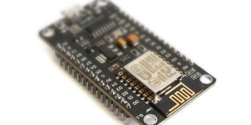
Most Arduino boards should work. I prefer the Nano – for me it’s the sweet spot for price, size and adaptability. But feel free to use your own favourite! As long as there are 7 digital I/O lines available, as well as the UART Rx/Tx lines if you want serial debugging, then you should be OK.
Buy Genuine Arduino Nano from Amazon
I only had a 3×4 keypad so that’s why I chose it for this project. You can use a 4×4 keypad but remember you’ll need an additional column I/O line so you’ll have to change the keypad_io.h header file.
Reverse-Engineering the Keypad Pinout
If you’re lucky you’ll have a keypad with labelled pins, or a datasheet detailing which pin is which. If you’re not, perhaps because you’ve salvaged the keypad from something else, or you found it at the bottom of a parts box, you may have to reverse engineer the pins. You can do this with a multimeter or a test circuit. The exact procedure is described here.
Once you have the pinout, it’s a simple matter of connecting the columns and rows up to the Arduino. Just be sure to get the order correct. If we number the 3 column pins on the keypad from 0 to 2 running left to right along the key matrix, and the 4 row pins from 0 to 3 running top to bottom, then the mapping should be as follows:-
Keypad Pin  | Port Pin | Arduino Nano Pin
----------- | -------- | ----------------
Column 0    | PB0      | 8
Column 1    | PB1      | 9
Column 2    | PB2      | 10
----------- | -------- |
Row 0       | PC0      | 14
Row 1       | PC1      | 15
Row 2       | PC2      | 16
Row 3       | PC3      | 17
NOTE If you use a different Arduino variant then the pin mapping may be different. Personally I avoid using Arduino pin numbering because I find it frustrating. I come from an embedded engineering background and never saw the problem with using traditional port numbering, such as PB0, PB1, etc. If you prefer to use the Arduino pin numbers then you’ll have to consult the reference for your particular board.
Schematic for the Matrix Keypad Decoder
I’ve included the schematic here for reference, using the Arduino Nano. The circuit is very simple and should be quite obvious, given the keypad mapping table above.


3 Responses