Using a Software Defined Radio to Debug LoRa Communication Problems
As part of my ongoing “Introduction to IoT” series, in this article you’ll learn how to use a cheap software defined radio (SDR) to diagnose problems between different LoRa radios and drivers.
SDR can be invaluable when diagnosing LoRa link problems, especially when using new and untested hardware and software.
What follows is an account of the many problems I had getting LoRa modules from different vendors to successfully talk to each other, and the way in which I debugged and solved each problem.
Using Different LoRa Radios & Drivers
You won’t be using LoRa for long before you start using different hardware and software solutions.
For instance, I started out prototyping with Heltec ESP32 LoRa modules a lot, because they’re incredible value for money, but when you find yourself installing a solar-powered node then they’re no good. The OLED display and on-board WiFi, even if you wanted them, are going to kill your battery life stone dead, so it’s time to start using different hardware.
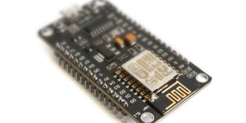
You might end up using one of the RFM95/RF95/RF9x modules. They’re based on the same Semtech SX1276 chip but use less power because they’ve got no extraneous power-hungry components.
If you fall into the same trap I did, you might end up installing the RadioHead library for the RFM95 because… well, because that’s what other people did.
When I did that, it took me an entire weekend to get a prototype working.
The RFM95 vs. the Heltec LoRa Module
I already had a simple LoRa to MQTT gateway running on a Heltec ESP32 module from an earlier project, so it should be easy to check that a new RFM95 node was sending the correct data… right?
Wrong. When I set everything up there was nothing at the receiver. Zilch. OK, well maybe not that unexpected, really. Debugging problems between a pair of comms devices is always hard because you can never be 100% sure which end is misbehaving.
I knew the Heltec module worked, but I’d hardly tested it thoroughly. So there was a fair chance it was at fault in some way, especially after some of the damning criticism Andreas Spiess has levelled at it in the past!
But, having foreseen this development, I had a contingency plan…
Contingency Plan: Use an SDR
If you’re a mere hobbyist with no access to fiendishly expensive test equipment, you have no way of knowing what’s enamating from that tiny wire antenna you’ve soldered to the LoRa module. Unless, that is, you get yourself an RTL-SDR module…
For the uninitiated, SDR stands for Software Defined Radio, and it’s possibly the coolest, smallest and cheapest piece of test equipment any wireless IoT enthusiast can own.
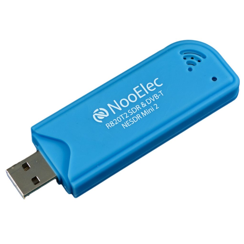
They can be found for less that $25 on Amazon: this Nooelec R820T model is the one I use and it just plugs into a USB port and connects to free software.
An SDR lets you examine and potentially demodulate pretty much any radio signal you’re ever likely to meet, from ham bands up to microwaves. People who are serious about SDR build specialised antennae for the bands they’re interested in, but for debugging LoRa you can just use the cheap antenna your SDR ships with.
Using SDR as a Software Spectrum Analyser
What’s great about SDR is the software that drives it. The most common is gqrx, but I’m on a Mac and I actually prefer an application called CubicSDR because I find the settings more intuitive.
The key thing about both applications is that they effectively work as a spectrum analyser, which is an otherwise hideously expensive piece of kit.
By setting the desired frequency and bandwidth (in my case, 868MHz and 125kHz, respectively), you can then actually see the output of the LoRa radio.
The modulation setting is not important because the SDR cannot automatically demodulate the spread-spectrum signal, but if you set it to FM then you can capture the signal as audio which can come in useful for manually decoding it if need be.
Later I’ll demonstrate how you can go way beyond this and actually see useful information directly in the RF spectrum, but first I just needed to check the RF95 transmitter was sending packets on the expected band.
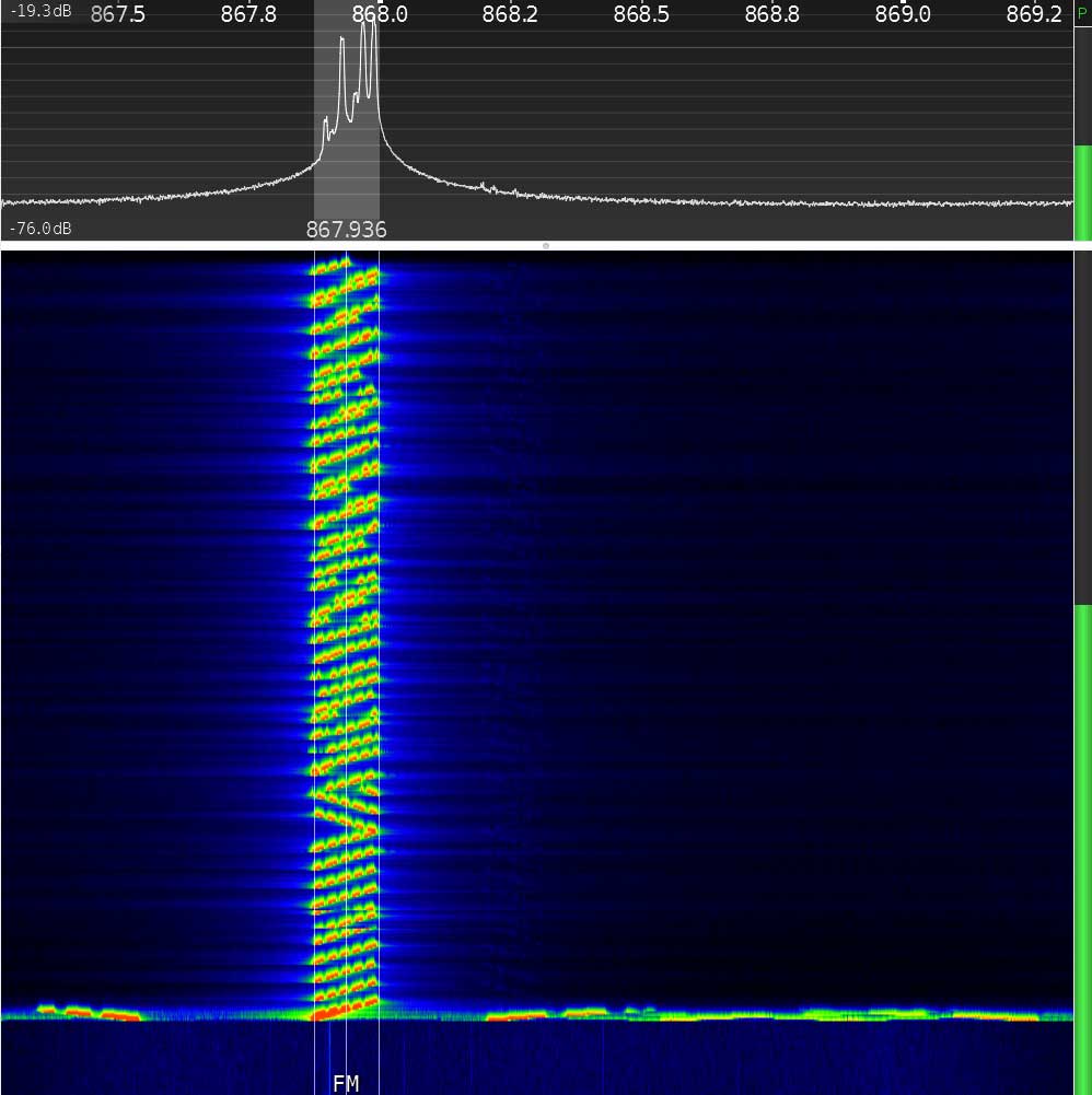
What a LoRa Packet Should Look Like on an SDR Spectrogram
I took a reference screenshot by listening to a Heltec ESP32 LoRa module configured as a transmitter, sending its factory default “hello” message. It looks like this:-
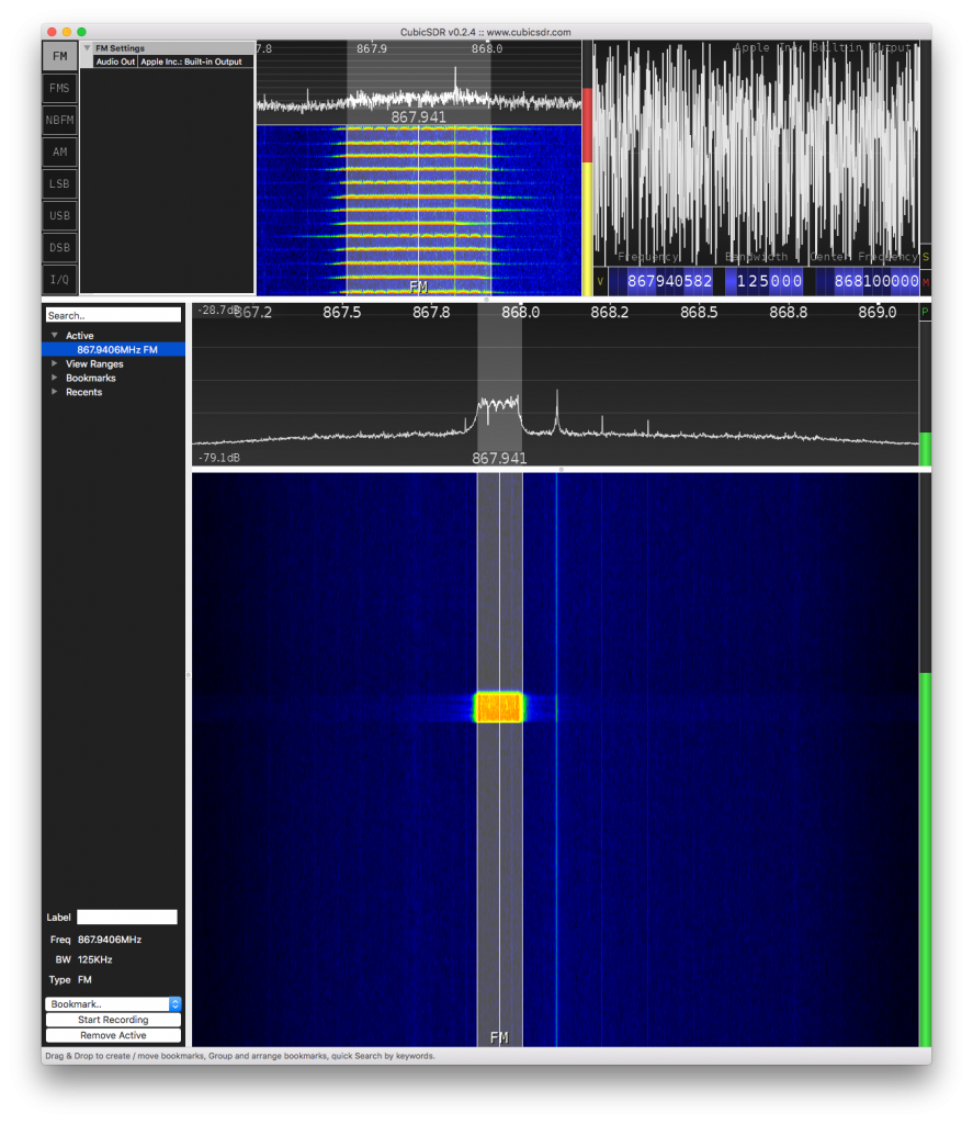
The large dark blue area in the lower part of the screen and the black area immediately above it are the parts we’re interested in. It’s called a spectrogram, or sometimes a “waterfall” chart.
It shows the power received at each frequency over time. The horizontal axis is frequency, as indicated by the white-on-black numbers about a third of the way down the screen, and the vertical axis is time.
The black area at the top shows the instantaneous power of the signals received at all the frequencies in the window.
The larger blue area shows the same thing, but represented in time: instead of the power being on the y axis, time is on the y axis and the power is shown as colour. Blue is basically noise, and red/yellow is a high power.
The narrow vertical band indicates the bandwidth and centre frequency. So the bright rectangular area near the centre is a packet of data transmitted with a 125 kHz bandwidth, centred on the frequency 867.941 MHz.
Downspread: Why the LoRa Band is Not Centred on the Nominal Frequency
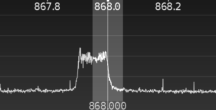
Why that strange frequency, you might be wondering? Well, you might notice the right edge of the band is at 868 MHz, which is the EU LoRa band. So why is it not centred on 868 MHz?
The screenshot below shows that the entire signal is spread across a 125kHz band (as expected), but rather than being centred on it, it’s immediately below the nominal 868 MHz.
This is called down spread and is normal for some spread spectrum modulation techniques, including LoRa. The reason is that radio’s clock source needs to be very accurate, and keeping the frequency as low as possible makes this easier.
The small reduction in frequency achieved by using the lower sideband rather than a centre band is worth it for the increased accuracy. (And clock accuracy is a real issue in LoRa, as you’ll see later in this article.)
Using SDR to Diagnose the Wrong LoRa Modulation Setting
When I fired up the RFM95 module, I expected to see something broadly similar. However, what I saw nothing like it. The power spectrum showed a single peak at 868 MHz, rather than the flat top you see with a spread spectrum.
This was so wrong that it was immediately obvious there was something amiss with the modulation. It didn’t even look vaguely like a LoRa spread spectrum. First of all I thought I had a broken radio, but I’d bought two (always a good idea in my experience), and a quick check showed the second radio behaved exactly the same.
I then remembered what I’d heard about some of these LoRa antennas being completely wrong for the job, so I removed the antenna I’d fitted and soldered on a wire antenna instead. This made zero difference so I figured it was not the issue.
So next I reasoned that there must be something seriously wrong with the register settings on the RFM95. Now I had to dig into the code and start reading datasheets – something I’d avoided until this stage!
My RadioHead Library Was Out Of Date
Very quickly it transpired the RadioHead library was setting the wrong bits in the ModemConfig1 register. And when I dug into the datasheet it became obvious why the modulation was wrong – it seems the RFM95 module can operate in two modes: LoRa mode, and FSK/OOK mode. The RadioHead library was setting the wrong mode!
Setting the modem config registers manually to what the data sheet said, the modulation then looked correct.
So I realised I had an old or just wrong version of the library. I can;t recall where I got the code from originally, but I went to the Adafruit-maintained Github repo, downloaded the correct library and checked the #defines in the RH_RF95.h file to ensure they matched the datasheet, which they did.
So the modulation was now fixed, but the receiver still did not decode the messages.
RadioHead and Heltec Use Different LoRa Sync Words
Despite fixing the modulation, the link was still broken. Weirdly, the occasional garbage packet was being picked up at the receiver, but the SDR showed the transmitter sending packets regularly on the correct band.
Some more reading around led to another discovery that was not obvious (at least, not to me): at the end of the preamble sequence, the LoRa protocol sends a sync word. The sync word is an 8-bit identifier that defines the network type.
The default sync word varies between different radios and driver libraries.
The Heltec radio uses a Semtech SX1276 radio which sets the sync word to 0x12 at power-on reset. The RFM95 is based on the same hardware, so the sync word defaults to the same.
However, this is where the similarities end. Looking in the library for the Heltec module, the sync word is set to 0x34, which is used by the LoRaWAN network:-
int LoRaClass::begin(long frequency, bool PABOOST)
{
   // ...
   setSyncWord(0x34);
   // ...
 }
The RadioHead library, on the other hand, has this comment in its setup code in the RH_RF95.cpp file:-
bool RH_RF95::init()
{
// ...// Set up default configuration// No Sync Words in LORA mode.
// ...
}
So the RFM95 module will keep its initial sync word of 0x12 and any data sent from the RFM95 will not be seen by the Heltec module. At least, that’s what you might expect…
Still Unresolved: LoRa Sync Words Do Not Seem 100% Reliable
However, LoRa sync words seem to behave strangely. Having them set differently actually still allows a small percentage of packets through! I have no idea why this is, aside from the possibility that some interference is causing the sync word to be corrupted, but the rate of acceptance seems too high to explain that. It is a known issue and may be a hardware problem.
So a small number of incoming packets were still arriving. They made no sense (yet), but they were being received, and they really added to the confusion.
Subsequently I discovered that the Heltec library that is installed via the Arduino IDE appears to be based (uncredited, with no license files) on Sandeep Mistry’s Arduino-LoRa source.
And importantly, I also found that the official repo has fixed the sync word issue, and it is no longer set to 0x34 in the LoRaClass::begin() method, but left at the default setting of 0x12 for a private LoRa network.
I fixed it by removing the line setSyncWord(0x34); from the LoRaClass::begin() method. This leaves the default at 0x12:-
int LoRaClass::begin(long frequency,bool PABOOST)
{
  // ...
  // 0x34 (LoRaWAN) is incorrect.
  //setSyncWord(0x34);
  // Leave at default 0x12 (private LoRa network) and let client decide if it needs to change.
Equally, calling LoRa.setSyncWord(0x12) from the client code would also fix the problem.
The Real Solution: Use Sandeep Mistry’s LoRa Library Instead of RadioHead
Sandeep Mistry’s LoRa library works equally well with the RFM95 module, and is smaller and far simpler to use. Configuration is few lines (even including error-checking):-
   LoRa.setPins(RFM95_CS, RFM95_RST, RFM95_INT);
   if (!LoRa.begin(RF95_FREQ_HZ)) {
     // failed
     while(1);
   }
   // otherwise all is good...
Still Not Fixed: the RadioHead Library has Longer Packets
Once the sync word was fixed, I was receiving garbage regularly and reliably at the gateway, which was at least something.
Nothing I could see in the modem configuration at either end could explain this. I tried changing CRC and implicit/explicit header mode, with varying results, but nothing fixed it.
So I decided it was time to examine the on-air packets using the SDR. But the data rate was too fast to examine in any detail.
The solution: slow everything down. Right down…
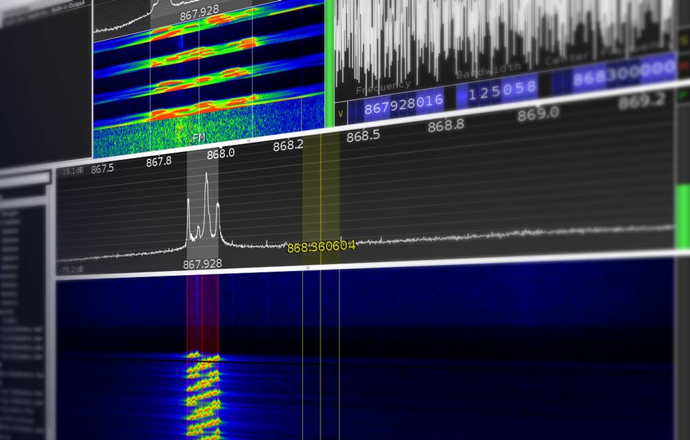
Increase the Spread Factor to Visually Inspect Packets Using SDR
The way you slow down the data in LoRa is by increasing the spreading factor. This increases the number of chips per symbol in the spread spectrum modulation. Without getting bogged down in spread spectrum theory, increasing the spreading factor from 7 to 12 slows down the data rate by 2^5 or 32 times.
What’s cool about this is that when you view the spectrogram on an SDR, you can actually see the on-air chirp patterns making up the symbols:-
This is really useful, because the chirps are clearly visible and if you were determined, you could work out the data from that alone. (In fact, there are easier ways.)
But keeping it simple for now, this view makes it really easy to check packet length. Simply take a screenshot and compare against a known good signal!
When I did that, I discovered the RFM95/RadioHead library was sending longer packets than the Heltec one. They seemed to be about 20% longer.
After experimenting some more with CRC and explicit/implicit payload settings, I concluded that the payload was actually longer: it wasn’t just a setting.
So I did something I should have done earlier: I dug into the RadioHead library’s source code.
There I discovered that the RH_RF95::send() function contains the following code:-
// The headersspiWrite(RH_RF95_REG_00_FIFO, _txHeaderTo);spiWrite(RH_RF95_REG_00_FIFO, _txHeaderFrom);spiWrite(RH_RF95_REG_00_FIFO, _txHeaderId);spiWrite(RH_RF95_REG_00_FIFO, _txHeaderFlags);
// the message data// The message dataspiBurstWrite(RH_RF95_REG_00_FIFO, data, len);spiWrite(RH_RF95_REG_22_PAYLOAD_LENGTH, len + RH_RF95_HEADER_LEN);
So the RadioHead library includes a mandatory, fixed-length header: that explains the longer packets!
I shamelessly ripped out the header lines, but then the length was wrong, so I had to make the following modification:-
// spiWrite(RH_RF95_REG_22_PAYLOAD_LENGTH, len + RH_RF95_HEADER_LEN);spiWrite(RH_RF95_REG_22_PAYLOAD_LENGTH, len);
LoRa Link Sometimes Works, But With Lots of CRC Errors
Removing the header seemed to improve the situation… slightly. Sometimes I saw a packet coming through successfully, but most of the time there was nothing.
Time to check the CRC settings.
The RxPayloadCrcOn bit in RegModemConfig (register 0x1E) was set, which means the transmitter will send a CRC on the uplink. When it receives a CRC, the receiver will automatically check it and reject any packet for which fails.
So I turned it off. At this point, the receiver started to receive data but it was mostly garbage, which basically proved the CRC check was failing. But the interesting thing was, the packet always turned to garbage on the same character, the fifth one received!
Now I was really stumped. I could not image why this could be. Until, that is, I hit Google. And one thing someone said in a forum caught my attention:-
When dealing with larger spreading factor and narrow bandwidth, it may require use of a higher precision TCXO crystal.
“Rick”, the Anarduino and HopeRF Community Forum
The current crystal used is a 10ppm, so if the bandwidth is < 125Khz and spreading factor > 11, the offset frequency may not meet the application requirements.
It was one of those OMG moments. Of course! I’d slowed down the data rate to 1/32nd its original speed, and the packet was taking so much longer to send. The radio has a cheap on-board clock (TCXO) that is now at the very edge of its tolerance. The fact it was consistently going wrong at the exact same point in the transmission now made total sense.
Finally Working!
I changed the spreading factor back to 7, my original setting before I’d started debugging with the SDR. I knew before I did it that it would work, and voila! The packets were received 100% reliably, even with the CRC turned back on.
Admittedly, if I wanted to use spreading factor 12 then I’d have a problem, but I’d only turned it on for debugging purposes so I wasn’t going to sweat that.
Conclusion
This tutorial has demonstrated how you can get a head start diagnosing LoRa communication problems using a cheap software-defined radio (SDR).
Thanks for Reading & Get In Touch
Did you find this useful? Have anything to add? I’d love to see your photos and hear your stories. Please send me feedback, either by leaving a comment below or by contacting me directly.
And if you’d like to receive updates about my upcoming projects, please join my mailing list.
You can also follow me on Twitter.


Thank you for the very interesting article.
Regards
Michael
Thank you for the positive feedback Michael. It’s always great to hear from readers!